Microbit Demos
Contents
Intro
The Tangible Interfaces Lab introduces interaction design using the BBC Microbit device and common sensors (see hardware). These code samples are meant to demonstrate functionality to help you get started exploring hardware interaction.
We code in JavaScript as it is a very common programming language. The Blocks style of coding has, in my experience, been more confusing than helpful. JavaScript programs are text, so it is easy to add // comments to explain the code. AI tools are very familiar with JavaScript, and can help to fix bugs or suggest features.
The Microbit is easy to program, no software needs to be installed. Connect the board to your computer with a USB cable and go to https://makecode.microbit.org for tutorials. You will be able to connect the board and program it from the webpage. It is possible to program the Microbit from the phone or tablet app, but it is harder.
Microbit
The Microbit is a credit card sized computer, with a surprising number of sensors and features built in. It can be programmed just with a web browser, and has a wide set of code extensions written to connect to various hardware. It is IMHO the fastest way to learn hardware making. Other computers such as Raspberry Pi, Arduino, or ESP32 (and many others) are more powerful, but require complex and fragile programming software which are often frustrating to students. Most of the concepts and components on the Microbit can be reused as you progress.
- Basic Microbit kit (Around $25 USD)
Introduction to Microbit
- https://makecode.microbit.org/#editor this is how you program the Microbit
- Microbit Getting Started
- Microbit Edge Connector pins
- Lessons
- More advanced sensor advice
More learning supports
- Youtube
- Reddit.com/r/microbit/
- Don’t forget our AI friends, they are excellent at translating technical language.
Microbit Component Kits
To design and prototype Tangible Interfaces, you’ll want a bunch of sensors to play with. A fun way to start are sensor packs. There are many variations, you will have to look at the parts you want. Here are a couple to get you started. Note that basic components are often labeled as “For Arduino”, but work with most micro-controllers, such as the Microbit.
- Example Sensor Pack
-
BBC Microbit with 45 in 1 Sensor Kit This is a handy kit with sensors that are known to work together. KeyeStudio model 4010
Microbit-only Projects
These programs work with the microbit alone, no wiring or components needed.
Microbit Button
The simplest Microbit program: The LEDs show a number. Button B increases the number, Button A reduces the number.
// The simplest Microbit program: shows a number on the LEDs.
// Button B increases the value, Button A decreases the value.
// No external wiring needed — just the micro:bit itself.

// --- Setup ---
let value = 0;
basic.showNumber(value);

// --- Button Handlers ---
input.onButtonPressed(Button.B, function () {
  value += 1;
  basic.showNumber(value);
});

input.onButtonPressed(Button.A, function () {
  value -= 1;
  basic.showNumber(value);
});
Compass
Reads the micro:bit’s built-in compass and displays an arrow on the LED screen pointing in the compass direction.
serial.writeValue("x", angle); sends the compass angle to the Microbit editor web page. Click “Show Data Device” on the left side of the editor to see this very handy way to get data out of the microbit.
// Reads the micro:bit's built-in compass
// Displays an arrow on the LED screen
// pointing in the compass direction
// (N, NE, E, SE, S, SW, W, NW).
// Microbit screen should face up.
// You may need to tilt the Microbit around to calibrate the compass

// --- Setup ---
let angle = 0;
basic.showIcon(IconNames.Triangle);
input.calibrateCompass();

// --- Main Loop ---
basic.forever(function () {
  angle = input.compassHeading();
  if ((angle >= 0 && angle < 45) || angle >= 360) {
    basic.showArrow(ArrowNames.North);
  } else if (angle >= 45 && angle < 90) {
    basic.showArrow(ArrowNames.NorthWest);
  } else if (angle >= 90 && angle < 135) {
    basic.showArrow(ArrowNames.West);
  } else if (angle >= 135 && angle < 180) {
    basic.showArrow(ArrowNames.SouthWest);
  } else if (angle >= 180 && angle < 225) {
    basic.showArrow(ArrowNames.South);
  } else if (angle >= 225 && angle < 270) {
    basic.showArrow(ArrowNames.SouthEast);
  } else if (angle >= 270 && angle < 315) {
    basic.showArrow(ArrowNames.East);
  } else if (angle >= 315 && angle < 360) {
    basic.showArrow(ArrowNames.NorthEast);
  } else {
  }
  serial.writeValue("angle", angle);
  basic.pause(100);
});
Shake
Very basic program to demonstrate one of the Microbit’s built in gestures.
// Shake the micro:bit to show a random number between 1 and 6 on the LED screen.

basic.pause(1000); // --- Setup ---
serial.redirectToUSB();
basic.showIcon(IconNames.Chessboard);
music.play(music.tonePlayable(262, music.beat(BeatFraction.Sixteenth)), music.PlaybackMode.UntilDone);

input.onGesture(Gesture.Shake, function () {
  // Runs when the micro:bit is shaken
  basic.showNumber(randint(1, 6));
  basic.pause(4000);
  basic.clearScreen();
});
Accelerometer Tilt Game
Tilt-to-navigate game: tilt the micro:bit to move a bright dot toward a dimmer target dot on the 5x5 LED grid. Press button A when you reach it to check.
// Tilt-to-navigate game:
// tilt the micro:bit to move a bright dot
// toward a dimmer dot on the 5x5 LED grid.
// Press button B when you reach it to win.

// --- Setup ---
// the LED screen has 5 pixels by 5 pixels
// these are numbered as 0 through 4
// the player starts in the top left LED
let player_x = 0;
let player_y = 0;

// the goal is in the center LED
let goal_x = 2;
let goal_y = 2;
serial.redirectToUSB();
music.play(music.tonePlayable(262, music.beat(BeatFraction.Sixteenth)), music.PlaybackMode.UntilDone);

// --- Main Loop ---
basic.forever(function () {
  basic.clearScreen();
  if (input.acceleration(Dimension.X) > 500) {
    player_x = Math.min(4, player_x + 1);
  } else if (input.acceleration(Dimension.X) < -500) {
    player_x = Math.max(0, player_x - 1);
  }
  if (input.acceleration(Dimension.Y) > 500) {
    player_y = Math.min(4, player_y + 1);
  } else if (input.acceleration(Dimension.Y) < -500) {
    player_y = Math.max(0, player_y - 1);
  }
  led.plotBrightness(player_x, player_y, 255);
  led.plotBrightness(goal_x, goal_y, 119);
  serial.writeLine("X" + input.acceleration(Dimension.X) + " " + "Y" + input.acceleration(Dimension.Y) + " " + "Z" + input.acceleration(Dimension.Z));
  basic.pause(100);
});

// --- Event Handlers ---
// Runs when button B is pressed to check if player reached the goal
input.onButtonPressed(Button.B, function () {
  if (player_x == goal_x && player_y == goal_y) {
    serial.writeString("WON");
    music.play(music.stringPlayable("C5 B A G F E D C ", 120), music.PlaybackMode.UntilDone);
    basic.clearScreen();
    basic.pause(1000);
    goal_x = randint(0, 4);
    goal_y = randint(0, 4);
  } else {
    music.play(music.tonePlayable(131, music.beat(BeatFraction.Sixteenth)), music.PlaybackMode.UntilDone);
    basic.clearScreen();
    basic.pause(1000);
  }
});
Simple Digital Input
Digital input is a yes/no or on/off measurement.
Simple External Button Component
Reads an external push button component — the simplest possible digital sensor, just on or off. Use this pattern any time you want a physical button separate from the micro:bit’s built-in A and B buttons.
// Reads an external push button and shows its state on the LED screen.
// This is the simplest possible digital sensor — just on or off.
// Use this pattern any time you want an physical button
//
// Physical setup:
//   Button module has 3 pins labeled S (signal), V (power), G (ground).
//   Connect S → micro:bit pin 0
//   Connect V → micro:bit 3V
//   Connect G → micro:bit GND
//
// Digital read: 0 = button pressed, 1 = button released.
// pin 0 is "pulled up" -a little electricity keeps the pin at 1
// Pressing the switch connects the pin to ground, "pulling" it to 0

// --- Setup ---
basic.showIcon(IconNames.SmallDiamond);
pins.setPull(DigitalPin.P0, PinPullMode.PullUp);

// --- Main Loop ---
basic.forever(function () {
  if (pins.digitalReadPin(DigitalPin.P0) == 0) {
    //Button is pressed"
    basic.showIcon(IconNames.Yes);
  } else {
    //Button is not pressed
    basic.clearScreen();
  }
  basic.pause(100); // wait 1/10th of a second
});
Knock Sensor
This code is also a simple digital switch, but demonstrates two new concepts. We are using an “event” code block that runs when a pin changes, and debouncing to avoid double counting knocks. You could use this to make a pedometer for the school of hard knocks.
// Reads a knock sensor and counts knocks on the LED screen.
// This is the simplest digital sensor — just on or off.
//
// This time we are using an event code block.
// The microbit is silently always checking if the pins are changing.
// If we write a special block of code called an evert, the microbit runs it when the change happens.
// This interrupts the basic.forever() loop, so we try to keep them short or we get confused.
//
// The knock sensor has 3 pins labeled S (signal), V (power), G (ground).
// Connect S → micro:bit pin 5
// Connect V → micro:bit 3V
// Connect G → micro:bit GND
//
// The sensor has a built-in pull-up resistor, so its signal is normally HIGH.
// A knock produces a brief LOW pulse  pins.onPulsed catches these brief signals.
// this is VERY fast.  So fast the springs will bounce back and forth a few times at 10x per second.
// this could look like 10 knocks, which is bad.
// so we

// Pin 5 is chosen for convenience for testing. Pressing Button A is also sets pins 5 to low

// --- Setup ---
basic.pause(1000);
basic.showIcon(IconNames.Chessboard);
basic.pause(1000);
basic.clearScreen();

pins.setPull(DigitalPin.P5, PinPullMode.PullNone); // Sensor has its own pull-up; PullNone avoids any conflict

let count = 0; // we are counting the knocks
let TimeSinceLastConnectToGround = 0; // we will use this to de-bounce the knock sensor
let knockRegistered = false; // flag to tell the forever loop to update the display

pins.onPulsed(DigitalPin.P5, PulseValue.Low, function () {
  // this runs when the pin 5 gets connected to ground, that is, the wire in the spring knock sensor bends and touches the other wire.
  let TimeSinceMicrobitStart = input.runningTime(); // now is the number of milliseconds since the microbit started
  let TimeSinceLastCheck = TimeSinceMicrobitStart - TimeSinceLastConnectToGround;
  TimeSinceLastConnectToGround = TimeSinceMicrobitStart; // always update — extends the quiet window on each bounce

  if (TimeSinceLastCheck > 150) knockRegistered = true;
});

basic.forever(function () {
  // this loop just updates the screen
  // you might notice that, in theory, we could just update the screen in the event loop
  // but basic.showNumber takes time, which interferes with the sensing
  // AI is your buddy on this kind of subtle problem.

  if (knockRegistered) {
    knockRegistered = false;
    count += 1;
    if (count > 9) count = 0;

    basic.showNumber(count); // display runs here, outside the event handler
  } else basic.pause(50); // wait a bit
});
Motion Sensor
Detects human movement using a PIR (passive infrared) sensor — it senses body heat moving in front of it. When motion is detected, the LED screen shows an eye icon and plays a tone. Wiring: signal → P0, VCC → 3V, GND → GND.
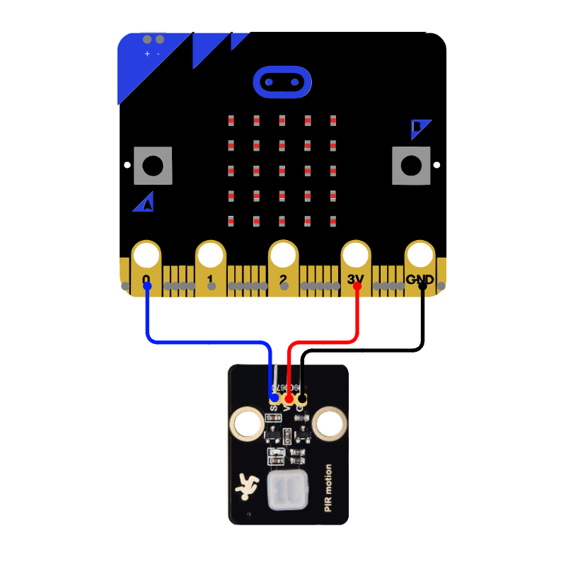
// Detects human movement using a PIR (passive infrared) motion sensor.
// When motion is detected, the LED screen shows an eye icon and plays a sound.
//
// How it works: the sensor detects body heat moving in front of it.
// Digital read: 1 = motion detected, 0 = no motion.
// The sensor has a ~2 second warm-up time when first powered on.
//
// Physical setup:
//   Sensor has 3 pins labeled S (signal), V (power), G (ground).
//   Connect S → micro:bit pin 0
//   Connect V → micro:bit 3V
//   Connect G → micro:bit GND

// --- Setup ---
basic.pause(2000);
music.play(music.tonePlayable(988, music.beat(BeatFraction.Eighth)), music.PlaybackMode.InBackground);
pins.setPull(DigitalPin.P0, PinPullMode.PullDown);
basic.showIcon(IconNames.Asleep);

// --- Main Loop ---
basic.forever(function () {
  if (pins.digitalReadPin(DigitalPin.P0) == 1) {
    basic.showIcon(IconNames.Happy);
    serial.writeLine("Motion detected!");
  } else {
    basic.showIcon(IconNames.Asleep);
    serial.writeLine("No motion");
  }
  basic.pause(100);
});
Capacitive Touch Sensor
Detects touch using a capacitive sensor — no mechanical button needed. Any conductive surface (metal, fruit, foil, water) can become a touch input.
// Detects touch using a capacitive touch sensor — no mechanical button needed.
// Touching the sensor pad lights up the LED screen
//
// Digital read: 1 = touched, 0 = not touched.
//
// Physical setup:
//   Sensor has 3 pins labeled S (signal), V (power), G (ground).
//   Connect S → micro:bit pin 0
//   Connect V → micro:bit 3V
//   Connect G → micro:bit GND
//   You can attach a wire to the sensor pad to extend the touch area.

// --- Setup ---
basic.pause(1000);
music.play(music.tonePlayable(988, music.beat(BeatFraction.Eighth)), music.PlaybackMode.InBackground);
pins.setPull(DigitalPin.P0, PinPullMode.PullDown);
basic.showIcon(IconNames.Heart);

// --- Main Loop ---
basic.forever(function () {
  if (pins.digitalReadPin(DigitalPin.P0) == 1) {
    basic.showIcon(IconNames.Yes);
    serial.writeLine("Touched!");
  } else {
    basic.showIcon(IconNames.SmallDiamond);
  }
  basic.pause(100);
});
Capacitive Touch
Detects touch using a single wire or small piece of metal. Note this is less reliable than an engineered component.
// Skin Capacitive switch — human skin activates. No sensor module needed.
//
// Physical setup:
//   Wire 1: micro:bit P0 → first conductive surface (what they touch)
//   No 3V or ground connection needed.
//
// Note!  Very finicky, may activate unexpectedly, especially with a long wire.

// --- Setup ---
basic.pause(1000);
music.play(music.tonePlayable(988, music.beat(BeatFraction.Eighth)), music.PlaybackMode.InBackground);
basic.showIcon(IconNames.Heart);
pins.touchSetMode(TouchTarget.P0, TouchTargetMode.Capacitive);
// --- Main Loop ---
basic.forever(function () {
  if (input.pinIsPressed(TouchPin.P0)) {
    basic.showIcon(IconNames.Yes);
    serial.writeLine("Touched!");
  } else {
    basic.showIcon(IconNames.SmallDiamond);
  }
  basic.pause(100);
});
Skin Conduction Switch
Human skin completes the circuit between two wires — no mechanical button or sensor module needed. A tiny amount of current flows through the body when a person bridges two conductors. Works with any two conductive surfaces: metal plates, door handle + floor mat, two strips of foil, fruit + foil.
// Skin conduction switch — human skin completes the circuit between two wires.
// No sensor module needed. Works with any two conductive surfaces a person bridges
// with their body: two metal plates, a handle + frame, fruit + foil, etc.
//
// How it works:
//   Capacitive mode with a GND reference wire held by the person.
//   The GND wire stabilizes the person's electric potential, making capacitive
//   detection reliable. TouchMode.Resistive does not work for skin.
//
// Physical setup:
//   Wire 1: micro:bit P0 → conductive surface (what they touch)
//   Wire 2: micro:bit GND → person holds this wire (bare wire, clip, or foil pad)
//   Touching the surface while holding GND triggers the sensor.
//
// Examples:
//   Two metal plates on a desk — bridge with fingertips
//   Door handle (P0) + floor mat (GND) — triggers when person grabs handle
//   Two strips of foil — touch both to trigger

// --- Setup ---
basic.pause(1000);
music.play(music.tonePlayable(988, music.beat(BeatFraction.Eighth)), music.PlaybackMode.InBackground);
basic.showIcon(IconNames.Heart);
pins.touchSetMode(TouchTarget.P0, TouchTargetMode.Capacitive);

// --- Main Loop ---
basic.forever(function () {
  if (input.pinIsPressed(TouchPin.P0)) {
    basic.showIcon(IconNames.Yes);
    serial.writeLine("Touched!");
  } else {
    basic.showIcon(IconNames.SmallDiamond);
  }
  basic.pause(100);
});
Hall Magnetic Sensor
Detects a nearby magnet using a Hall effect sensor. Magnets can be hidden inside objects, behind walls, or under surfaces to create invisible triggers — this simple sensor is used everywhere in devices, cars, and homes.
// Detects a nearby magnet using a Hall effect magnetic sensor.
// Magnets can be hidden inside objects, behind walls, or under surfaces
// to create invisible triggers — no visible button or switch needed.
//
// Sensor output depends on the sensor type
// in this case we use a sensor that goes low (== 0) when a magnet is presnt.
// try it with yours to explore

// Try taping a small magnet to a game piece, box lid, or sliding panel.
//
// Physical setup:
//   Sensor has 3 pins labeled S (signal), V (power), G (ground).
//   Connect S → micro:bit pin 0
//   Connect V → micro:bit 3V
//   Connect G → micro:bit GND
//   Hold a magnet close to the sensor face to trigger it.

// --- Setup ---
basic.pause(1000);
basic.showIcon(IconNames.Chessboard);
pins.setPull(DigitalPin.P0, PinPullMode.PullUp);
music.play(music.tonePlayable(784, music.beat(BeatFraction.Eighth)), music.PlaybackMode.InBackground);
let magnetIsPresent = false;

// --- Main Loop ---
basic.forever(function () {
  magnetIsPresent = pins.digitalReadPin(DigitalPin.P0) == 0;

  if (magnetIsPresent) {
    basic.showIcon(IconNames.Yes);
    serial.writeLine("Magnet detected!");
  } else {
    basic.clearScreen();
  }
  basic.pause(100);
});
Motors
Servo simple
Sweeps a servo motor back and forth from 0 to 180 degrees continuously.
/*
A basic demo of servo movement
Sweeps a servo motor back and forth from 0 to 180 degrees continuously.

NOTE if writing a new microbit program, go to Extensions and search for "Servo" and add it.

Physical setup for typical microservo
They typically come with a 3 wire ribbon
Orange wire → micro:bit pin 0
Red wire → micro:bit 3V
Brown wire→ micro:bit GND
*/

// --- Setup ---
basic.pause(1000);
basic.showIcon(IconNames.Chessboard);

servos.P0.setRange(0, 180);
let direction = 1;
let angle = 0;
basic.clearScreen();

basic.forever(function () {
  // --- Main Loop ---
  if (angle > 180 || angle < 0) {
    direction = direction * -1;
  }
  angle += direction;
  servos.P0.setAngle(angle);
  serial.writeValue("angle", angle);
});
Steering Servo
Steers a servo motor up and down using buttons A and B. A simple demo of using buttons to control physical output.
// A simple demo: steers a servo motor with buttons A and B.

let rotation = 100; //
servos.P1.setRange(0, 180);

basic.forever(function () {
  // --- Main Loop ---
  servos.P1.setAngle(rotation);
  basic.pause(200);
});

input.onButtonPressed(Button.A, function () {
  // Button A moves the servo clockwise

  if (rotation < 180) {
    rotation += 10;
  }
});

input.onButtonPressed(Button.B, function () {
  // Button B moves the servo counter clockwise
  if (rotation > 0) {
    rotation += -10;
  }
});
Control Servo with analog sensor
Controls a servo motor position using an analog sensor input. The sensor reading on P1 is mapped to a servo angle on P0.
/*
Servo steered by an Analog Sensor
The basic potentiometer module (rotational varible resistor) is an intuitive control
What other input might you use?
See the Sonar Servo demos)

No extensions required — uses built-in micro:bit blocks only.

Physical setup:

Analog sensor
S pin to Microbit Pin 0
V pin to Voltage
G pin to Ground

Servo
Orange Wire to Microbit Pin 1
Red Wire to voltage
Brown Wire to Ground
*/

basic.pause(1000); // prevent LED flash when programming
basic.showIcon(IconNames.Chessboard); // --- Setup ---
serial.redirectToUSB();

basic.forever(function () {
  // --- Main Loop ---
  let servo = Math.map(pins.analogReadPin(AnalogReadWritePin.P0), 0, 1023, 0, 180);
  led.plotBarGraph(servo, 180);
  pins.servoWritePin(AnalogPin.P1, servo);
  serial.writeLine("" + servo);
});
Servo with Finger Bend Sensor
Controls a servo motor position using another analog sensor, the flex bend sensor you can attach to a glove. The sensor reading on P1 is mapped to a servo angle on P0.
/*
  Flex Sensor — Finger Bend to Servo Gripper
  Reads a flex sensor on Pin P0.
  Maps finger bend to a servo on Pin P1.
  Straight finger = open gripper (0°). Bent finger = closed gripper (180°).

  Wiring:
    - Flex sensor: one end to 3.3V, other end to P0
  - 47kΩ resistor one end to P0 , other end to GND
  - Servo: orange → P1, red → 3.3V, brown → GND
*/

basic.pause(1000);
basic.showIcon(IconNames.Chessboard);
serial.redirectToUSB();

// Calibrate first: bend and straighten your finger while watching serial output.
// Set these to match your actual readings.
const FLEX_STRAIGHT = 700; // reading when finger is straight (sensor flat)
const FLEX_BENT = 300; // reading when finger is fully bent

basic.forever(function () {
  let flexReading = pins.analogReadPin(AnalogPin.P0);

  let servoAngle = Math.map(flexReading, FLEX_STRAIGHT, FLEX_BENT, 0, 180); //convert the current value in the range of FLEX_STRAIGHT to FLEX_BENT, map it to the servo range
  servoAngle = Math.max(0, Math.min(180, servoAngle)); // limit values to safe range for servo

  pins.servoWritePin(AnalogPin.P1, servoAngle);
  led.plotBarGraph(flexReading, 1023);
  serial.writeLine("flex: " + flexReading + " | servo: " + Math.round(servoAngle));
  basic.pause(50);
});
The same modules, with more complex code to smooth out the natural variations in sensor movement.
/*
  Flex Sensor with Smoothing — Finger Bend to Servo Gripper
  Reads a flex sensor on Pin P0, applies moving average smoothing,
  maps smoothed finger bend to a servo on Pin P1.
  Straight finger = open gripper (0°). Bent finger = closed gripper (180°).

  Wiring:
    - Flex sensor: one end to 3.3V, other end to P0
    - 47kΩ resistor: one end to P0, other end to GND
    - Servo: orange → P1, red → 3.3V, brown → GND

  HOW TO CALIBRATE:
    Run the sensor and watch "raw" in the serial output.
    Hold finger straight → note the value → set FLEX_STRAIGHT
    Bend finger fully → note the value → set FLEX_BENT
*/

basic.pause(1000);
basic.showIcon(IconNames.Chessboard);
serial.redirectToUSB();

// --- Calibration (update after observing your sensor) ---
const FLEX_STRAIGHT = 700; // reading when finger is straight
const FLEX_BENT = 300;     // reading when finger is fully bent

// --- Moving Average Setup ---
let readings_history: number[] = [];
const readings_history_size = 3; // lower = more responsive, higher = smoother
/*
  2–3 = responsive, good for servo control
  5   = smooth balance (try this if servo feels jittery)
  10  = very smooth, but lags behind fast bends
*/

const FLEX_MIN = Math.min(FLEX_BENT, FLEX_STRAIGHT);
const FLEX_MAX = Math.max(FLEX_BENT, FLEX_STRAIGHT);
let midpoint = Math.round((FLEX_MIN + FLEX_MAX) / 2);
for (let i = 0; i < readings_history_size; i++) {
  readings_history.push(midpoint);
}

// --- Output Variables ---
let raw_sensor_value = 0;
let smoothed_value = midpoint;
let servoAngle = 0;

// --- Main Loop ---
basic.forever(function () {
  raw_sensor_value = pins.analogReadPin(AnalogPin.P0);

  // Step 1: Range filter — ignore readings outside the calibrated sensor range
  if (raw_sensor_value < FLEX_MIN || raw_sensor_value > FLEX_MAX) {
    serial.writeLine("raw=" + raw_sensor_value + "  [out of range, skipping]");
    return;
  }

  // Step 2: Moving average — add new reading, drop oldest
  readings_history.push(raw_sensor_value);
  if (readings_history.length > readings_history_size) {
    readings_history.shift();
  }
  let sum = 0;
  for (let i = 0; i < readings_history.length; i++) {
    sum += readings_history[i];
  }
  smoothed_value = Math.round(sum / readings_history.length);

  // Step 3: Map smoothed value to servo angle
  servoAngle = Math.map(smoothed_value, FLEX_STRAIGHT, FLEX_BENT, 0, 180);
  servoAngle = Math.max(0, Math.min(180, servoAngle));

  pins.servoWritePin(AnalogPin.P1, servoAngle);
  led.plotBarGraph(smoothed_value, 1023);
  serial.writeLine("raw=" + raw_sensor_value + "  smoothed=" + smoothed_value + "  servo=" + Math.round(servoAngle));

  basic.pause(50);
});
Fan Module
Controls an L9110 fan module for physical, tactile output — you can feel the wind on your skin. Button A turns the fan forwards, Button B turns it reverse, Touch Logo stops fan.
/*
Controls a fan module — a small motor with a propeller that blows air.
The microbit pins are not strong enough to power the motor
so the module has a L9110, a small chip common for controlling motors

Button A turns the fan forwards
Button B turns it reverse
Touch Logo stops fan

Physical setup:
  Fan module has 4 pins: INA, INB, VCC, GND.
  Connect INA → micro:bit pin 0
  Connect INB → micro:bit pin 1
  Connect VCC → micro:bit Voltage
  Connect GND → micro:bit GND

  The fan may be very weak using just microbit power
  you may want to use additional battery power
*/

// --- Setup ---
basic.pause(1000);
basic.showIcon(IconNames.Chessboard);
pins.digitalWritePin(DigitalPin.P0, 0); // Make sure fan starts off
pins.digitalWritePin(DigitalPin.P1, 0); // Make sure fan starts off

input.onButtonPressed(Button.A, function () {
  // Button A: turn fan on
  pins.digitalWritePin(DigitalPin.P0, 1);
  pins.digitalWritePin(DigitalPin.P1, 0);
  basic.showArrow(ArrowNames.West);
  serial.writeLine("Fan forwards");
});

input.onButtonPressed(Button.B, function () {
  // Button B: turn fan off
  pins.digitalWritePin(DigitalPin.P0, 0);
  pins.digitalWritePin(DigitalPin.P1, 1);
  basic.showArrow(ArrowNames.East);
  serial.writeLine("Fan backwards");
});

input.onLogoEvent(TouchButtonEvent.Pressed, function () {
  // Stop Fan
  pins.digitalWritePin(DigitalPin.P0, 0);
  pins.digitalWritePin(DigitalPin.P1, 0);
  basic.showIcon(IconNames.No);
  serial.writeLine("Fan stop");
});
Fan Module with speed control
Same set up as previous, but now we can increase the speed with the B button and decrease with the A button. Touch the logo to stop. This demonstrates analogWritePin, which is another term for PWM (Pulse Width Modulation) This is simply turning the pin on and off very very fast to simulate it being partially on. This technique is very widely used in hardware, for example to dim LED lights.
/*
Controls a fan module — a small motor with a propeller that blows air.
The microbit pins are not strong enough to power the motor
so the module has a L9110, a small chip common for controlling motors

Button A reduces the speed, even going backwards
Button B increases the speed
Touch Logo stops fan

Physical setup:
  Fan module has 4 pins: INA, INB, VCC, GND.
  Connect INA → micro:bit pin 0
  Connect INB → micro:bit pin 1
  Connect VCC → micro:bit Voltage
  Connect GND → micro:bit GND

  The fan may be very weak using just microbit power
  you may want to use additional battery power
*/

// --- Setup ---
basic.pause(1000);
basic.showIcon(IconNames.Chessboard);
pins.digitalWritePin(DigitalPin.P0, 0); // Make sure fan starts off
pins.digitalWritePin(DigitalPin.P1, 0); // Make sure fan starts off
let speed = 0; // speed can go from -100  to +100
let speedIncrement = 10; // how much we change the speed each button click

input.onButtonPressed(Button.A, function () {
  // Button A: decrease the fan speed
  speed -= speedIncrement; // reduce one increment of speed
  if (speed < -100) speed = -100; // keep the speed in bounds
  changeSpeed();
  basic.showArrow(ArrowNames.South);
  serial.writeLine("Fan- speed=" + speed);
});

input.onButtonPressed(Button.B, function () {
  // Button A: increase the fan speed
  speed += speedIncrement; // increase one increment of speed
  if (speed > 100) speed = 100; // keep the speed in bounds
  changeSpeed();
  basic.showArrow(ArrowNames.North);
  serial.writeLine("Fan+ speed=" + speed);
});

input.onLogoEvent(TouchButtonEvent.Pressed, function () {
  // Stop Fan
  speed = 0;
  changeSpeed();
  serial.writeLine("Fan stop");
});

function changeSpeed() {
  // briefly stop the pins (so fast no one will notice!).
  // This is to prevent the motor from trying to go both ways

  pins.digitalWritePin(DigitalPin.P0, 0); // turn off the pin
  pins.digitalWritePin(DigitalPin.P1, 0); // turn off the pin

  let analogSpeed = Math.map(Math.abs(speed), 0, 100, 0, 1023); // convert speed variable into a output value

  if (speed > 0) {
    pins.analogWritePin(AnalogPin.P0, analogSpeed);
  } else if (speed < 0) {
    pins.analogWritePin(AnalogPin.P1, analogSpeed);
  }
}
Relay Module
Controls a relay — an electrically operated switch that lets your micro:bit turn real-world devices on and off (lamps, fans, motors). You’ll hear a satisfying “click” when it switches. Button A = on, Button B = off.
/*
Controls a relay module — an electrically operated switch that can turn
real-world devices on and off. You'll hear a satisfying "click" when it switches.
A relay lets your micro:bit control things like lamps, fans, or motors
that need more power than the micro:bit can provide directly.

PLEASE be extremely careful if you are using higher voltage components!!!

Button A turns the relay on (click!), Button B turns it off.
Digital write: 1 = relay ON (closed circuit), 0 = relay OFF (open circuit).

Physical setup:
Relay module has 3 low-voltage pins: S (signal), V (power), G (ground).
Connect S → micro:bit pin 0
Connect V → micro:bit 3V
Connect G → micro:bit GND

The relay also has screw terminals for the high-voltage side:
COM (common), NO (normally open), NC (normally closed).
For basic testing, just listen for the click — no need to wire the screw terminals.
To control a device: wire it through COM and NO so it turns on when the relay activates.
*/

// --- Setup ---
basic.pause(1000);
basic.showIcon(IconNames.Chessboard);
pins.digitalWritePin(DigitalPin.P0, 0);

// --- Event Handlers ---
input.onButtonPressed(Button.A, function () {
  // Button A: turn relay on
  pins.digitalWritePin(DigitalPin.P0, 1);
  basic.showIcon(IconNames.Yes);
  serial.writeLine("Relay ON");
});

input.onButtonPressed(Button.B, function () {
  // Button B: turn relay off
  pins.digitalWritePin(DigitalPin.P0, 0);
  basic.showIcon(IconNames.No);
  serial.writeLine("Relay OFF");
});
Analog Sensors
‘Analog’ today is thought of as the opposite of digital, but its original meaning was a computer worked as an “analogy” of reality. The book “Building SimCity” has a fantastic exploration into the early days of simulation and computing.
‘Analog’ input typically means the microbit compares the voltage on a pin compared to the power voltage. The microbit does not know the actual voltage, it knows the proportion. You may notice that the microbit requires 3.3v, but you can power with 2 AA batteries. This means it will still work when the voltage changes slightly, even as the battery depletes (up to a point).
Many simple sensors will communicate the output by ‘dividing’ the voltage, sending part to the input pin and the rest to ground. This is why many packaged sensors need a voltage and a ground pin, in addition to the sensor pin.
Voltage Divider Sensors
If the sensor has only 2 pins, for example, the flex sensor, one would connect one leg to power, the second to the pin, but also add a resistor from the pin to ground. This set up is called a “voltage divider”. The proportion of the sensor’s resistance to the fixed resistor determines the voltage range.
Some experimentation is often necessary to find the ideal resistor for your sensor!
- Using a resistor value that is roughly equal to the sensor’s average resistance during use will give you the widest range of numbers (e.g., a reading of 200 when flat vs. 800 when bent).
- Higher resistance values (like 47kΩ or 100kΩ) pull less current from your battery, which is ideal for wearable or portable projects.
- If you place the fixed resistor between the Analog Pin and Ground (pull-down), the voltage reading will decrease as you bend the sensor (because the sensor’s resistance increases). This works in reverse if you put the resistor to power.
For the Microbit, one reads the voltage like so:
AnalogReading = pins.analogReadPin(AnalogPin.P0);
This returns a value from 0 to 1023. The microbit is slicing the input voltage into 1024 slices and telling you the number.
Side note: 1023 is not a random number; 1024 is a common number in computing; 10 bits gives you 1024 combinations. You may recognize 1024x768 as a monitor resolution. 10 bits was chosen as a “good enough” precision for most users. Higher resolution sensors will slice the measurement more finely.
A key detail to understand is that the microbit does not know the absolute measurement of the sensor, or even the voltage, it just knows the proportion.
Finally, each sensor will have its own behavior, it will default to a certain number at rest, and max out at another number, not necessarily from 0-1023. To make it easier to understand, we ‘normalize’ the measurement to 0 to 100%. We might write this as:
AnalogReading = pins.analogReadPin(AnalogPin.P0);

value_at_rest = 200;      // discovered through testing
value_at_max_bend = 800;  // discovered through testing

percentage = Math.map(AnalogReading, value_at_rest, value_at_max_bend, 0, 100);
percentage = Math.constrain(percentage, 0, 100);  // clamp if sensor exceeds tested range
percentage = Math.round(percentage);
It is our job as designers to test the start / end points of the sensors and ‘design’ the input range to output behavior. For example, we can determine value_at_rest and value_at_max_bend using the basic analog sensor code example below to print raw values while moving the sensor.
Note the measurement is usually not linear (proportional from the physical input). You might define different ranges with different meanings, for example, three ranges of partially bent flex sensor.
5v Sensors on a 3.3v Microbit ??
This is slightly more advanced, but people are naturally confused when examples break rules we just introduced.
Some sensors need higher voltage. The Gas sensor needs 5 volts to run its heating element. You may notice that at 100% the sensor would output 5 volts, above the 3.3v that the Microbit can handle. Indeed, putting 5 volts to a microbit pin would damage the board. It is possible, perhaps even common, to “burn out” a single pin. Many new experimenters have experienced this confusion.
One surprising detail is people will sometimes just use the wrong voltage knowing that the sensor is made to rarely (not never!) send all 5 volts. Its sweet spot could be midrange of 5v, which is fine for 3.3 volts. This would be considered a smart hack, with an acceptable amount of risk. I’m not smart enough to calculate out that risk! However, if you use a common component, and check online forums, you will find many examples to help.
Another solution is to make a voltage divider to reduce all voltage levels by 1/3, turning 5v to 3.3v. Unfortunately, this reduces all the voltage, so you may lose sensitivity on the low end. No free lunch!
Gas Sensor 5 volt S pin ──── 10kΩ ──── micro:bit P0
                                │
                              15kΩ
                                │
                               GND
Basic Analog sensor
Reads an analog sensor on pin P0 and displays the value as a bar graph on the LED screen. An example sensor is the “potentiometer” (a rotating variable resistor) that changes the voltage that the microbit sees.
/*
Reads an analog sensor on pin P0
Displays the value as a bar graph on the LED screen
Send the raw value and percentage to the computer.
*/

basic.pause(1000); // Start up
basic.showIcon(IconNames.Chessboard);
let AnalogReading = 0;

basic.forever(function () {
  // --- Main Loop ---
  AnalogReading = pins.analogReadPin(AnalogPin.P0);
  led.plotBarGraph(AnalogReading, 1023);
  serial.writeLine("Analog Reading " + AnalogReading + "|" + Math.round(Math.map(AnalogReading, 0, 1023, 0, 99)) + "%");
  basic.pause(100);
});
Pressure/Force Sensor
Reads a thin-film pressure sensor and shows how hard you’re pressing as a bar graph. Unlike a button (on/off), this sensor gives an analog value of the pressure is applied.
/*
Reads a thin-film pressure (force) sensor and displays how hard you're pressing.
Unlike a button (on/off), this sensor gives an analog value — it knows HOW MUCH
force is applied. Squeeze harder = higher reading.
Use cases: squeeze toys, sit-on sensors, footstep detection, grip strength.

Physical setup:
Sensor has 3 pins labeled S (signal), V (power), G (ground).
Connect S → micro:bit pin 0
Connect V → micro:bit 3V
Connect G → micro:bit GND
Press the round film area with your finger to see values change.
*/

basic.pause(1000); // Start up
basic.showIcon(IconNames.Chessboard);
let forceReading = 0;

basic.forever(function () {
  // --- Main Loop ---

  forceReading = pins.analogReadPin(AnalogPin.P0);
  led.plotBarGraph(forceReading, 1023);
  serial.writeLine("forceReading " + forceReading + "|" + Math.round(Math.map(forceReading, 0, 1023, 0, 99)) + "%");
  basic.pause(100);
});
Joystick Input
Reads an analog joystick and displays position as a dot on the LED screen. Pressing the joystick button plays a sound.
The joystick is actually simply 2 rotating variable resistors, with springs to return them to the center.
/*
 Reads an analog joystick and displays x and y position as a dot on the LED screen.
 Pressing the joystick button plays a sound.

 Wiring: Y direction → pin 0, X direction → pin 1, Switch → pin 2
 MAP scales the 0-1023 input to 0-4 (pixel positions on the LED grid)
 ROUND converts to whole numbers for LED coordinates
 Digital read pin 2: 1 = button clicked
*/

basic.pause(1000); // Start up
serial.redirectToUSB();
basic.showIcon(IconNames.Chessboard);
let Y = 0;
let X = 0;

// --- Main Loop ---
basic.forever(function () {
  basic.clearScreen();
  X = Math.round(Math.map(pins.analogReadPin(AnalogReadWritePin.P1), 0, 1023, 4, 0));
  Y = Math.round(Math.map(pins.analogReadPin(AnalogReadWritePin.P2), 0, 1023, 0, 4));
  if (pins.digitalReadPin(DigitalPin.P0) == 1) {
    music.play(
      music.createSoundExpression(WaveShape.Sine, 5000, 0, 255, 0, 500, SoundExpressionEffect.None, InterpolationCurve.Linear),
      music.PlaybackMode.InBackground,
    );
    basic.showIcon(IconNames.SmallDiamond);
  } else {
    led.plotBrightness(X, Y, 255);
  }
  basic.pause(100);
  serial.writeNumbers([X, Y, 0]);
});
Ultraviolet Sensor
When should you reapply sunscreen? This example reads a GUVA-S12SD UV sensor and estimates the UV index (0-11). A similar product page states “You can convert the voltage to UV Index by dividing by 0.1V. So if the output voltage is 0.5V, the UV Index is about 5.
/*
Reads a GUVA-S12SD ultraviolet (UV) sensor and estimates the UV index.
UV index 0-2 is low, 3-5 moderate, 6-7 high, 8-10 very high, 11+ extreme.
Great for wearable projects: when should you reapply sunscreen?

Analog read: the sensor outputs a voltage proportional to UV intensity.
Formula: UV Index = voltage / 0.1V (linear, per Adafruit GUVA-S12SD spec).

Physical setup:
  Sensor has 3 pins labeled S (signal), V (power), G (ground).
  Connect S → micro:bit pin 0
  Connect V → micro:bit 3V
  Connect G → micro:bit GND
  Point the sensor window toward the sky or a UV light source.
*/

basic.pause(1000); // Start up
serial.redirectToUSB();
basic.showIcon(IconNames.Chessboard);

let analogInput = 0;
let uvVoltage = 0;
let uvIndex = 0;

basic.forever(function () {
  // --- Main Loop ---
  // Step 1: Read the raw sensor value (0 to 1023)
  analogInput = pins.analogReadPin(AnalogPin.P0);

  // Step 2: Convert to voltage — micro:bit reads 0–3.3V as 0–1023
  uvVoltage = (analogInput / 1023) * 3.3;

  // Step 3: Convert voltage to UV index — sensor outputs 0.1V per UV index unit
  uvIndex = Math.round(uvVoltage / 0.1);

  basic.showNumber(uvIndex); // Show the UV index number on the LED screen

  serial.writeLine("raw " + analogInput + "  |  voltage: " + uvVoltage + "V  |  uvIndex: " + uvIndex);
  basic.pause(1000);
});
Analog Alcohol Sensor
Reads an MQ-3 alcohol sensor that detects alcohol vapor in the air. Try holding hand sanitizer near the sensor. Needs 5V and a few minutes to warm up.
The sensor ‘works’, it detects alcohol. It also demonstrates the extreme difficulty of engineering a device with life and death consequences.
If you test it, you will see that the device takes a while to warm up, it takes a while to respond and the sensor takes a while to “de-respond”. In addition, calculating blood alcohol level from alcohol in the air is no simple matter. For example, you need a dependable background to compare it to.
We can’t simply say “an analog reading above 700 = drunk” because the sensor reading needs to be compared to the air in the room. If that room is a biker bar, you will get a different base measurement than outside. Temperature affects the atomization of alcohol, etc, etc.
Even professional machines have been shown to have engineering errors. Machines marketed as precise to the third decimal place were found to produce results that were sometimes 40% too high. NY Times Article “These Machines Can Put You in Jail. Don’t Trust Them.”
This is not to say the sensor does not ‘work’ but that the way they work is often a complex and under-defined question that a designer needs to engage deeply with.
/*
MQ-2 alcohol sensor - Use to detect hand sanitizer or other alcohol. The sensor heats up during use. This is normal.

Wiring:
MQ-2 VCC to 5V
MQ-2 GND → GND
MQ-2 A0  → micro:bit pin 0
Microbit VCC → 3.3V (not 5V — the analog output follows VCC and will exceed micro:bit's pin limit at 5V)
Microbit GND → GND

Phases:
  Warmup   — 90 seconds for sensor to stabilize. Press A to skip if already warm.
  Calibrate — press A to record clean-air baseline (averages 10 readings over 5 seconds)
  Measure  — bar graph shows rise above baseline; serial shows raw values
*/

basic.pause(1000);
basic.showIcon(IconNames.Chessboard);
const CALIBRATE_SAMPLES = 10;
const WARMUP_TICKS = 180; // 90 seconds at 500ms per tick
let baseline = 0;
let IsWarmedUp = false;
let ticks = 0;

input.onButtonPressed(Button.A, function () {
  IsWarmedUp = true; // give user option to skip warmup, fo example if restarting program
});

basic.forever(function () {
  let reading = pins.analogReadPin(AnalogPin.P0);
  if (IsWarmedUp == false) {
    ticks += 1;
    serial.writeValue("warmup", reading);
    if (ticks >= WARMUP_TICKS) {
      IsWarmedUp = true;
      basic.showString("Press A");
    }
  } else if (input.buttonIsPressed(Button.A)) {
    // is button a pressed?  stop and take sample calibration
    basic.showIcon(IconNames.SmallDiamond);
    let sum = 0;
    for (let i = 0; i < CALIBRATE_SAMPLES; i++) {
      sum += pins.analogReadPin(AnalogPin.P0);
      basic.pause(500);
    }
    baseline = sum / CALIBRATE_SAMPLES;
    serial.writeValue("baseline", baseline);
    basic.showIcon(IconNames.Yes);
  } else {
    // normal usage mode

    led.plotBarGraph(reading - baseline, 1023 - baseline);
    serial.writeLine("gas: " + reading + "  base: " + baseline);
  }

  basic.pause(500);
});
Sensors with Extensions
The MakeCode editor has the ability to use code from experience programmers, called extensions. These can be written in a more complex language to do actions too complicated for beginners. This is common in programming. In fact, most programming involves stitching together code from previous generations of programmers.
Ultrasonic Distance Sensor
Reads an ultrasonic distance sensor (HC-SR04) and displays the distance as a bar graph on the LED screen. In the microbit code editor, open “extensions”, search for ‘Sonar’ and add. Example project Example video
/*
Reads an ultrasonic distance sensor (HC-SR04) and displays the distance
as a bar graph on the LED screen and logs distance values over serial.

This is a widely used sensor for small learning robots, but is very basic.
It can sense an object target larger than a pen up to a wall.
But is not a camera, it just knows if something is there, not its shape
or if there are multiple objects.

For background, the ultrasonic distance sensor works like a bat.
It sends a sound "ping" and counts the time for the echo.
The trig pin triggers the ping (output from micro:bit to sensor).
The echo pin receives the return signal (input from sensor to micro:bit).

Note if writing a program from scratch, add the "Sonar" extension in Makecode editor.
*/

basic.pause(1000); // --- Setup ---
basic.showIcon(IconNames.Chessboard);
serial.writeLine("Start Ultrasonic Sensor");
let DistanceInCM = 0;
let trigPin = DigitalPin.P1; // connect to the trig pin on the distance sensor
let echoPin = DigitalPin.P0; // connect to the echo pin on the distance sensor

basic.forever(function () {
  // --- Main Loop ---
  DistanceInCM = sonar.ping(trigPin, echoPin, PingUnit.Centimeters);

  if (DistanceInCM == 0) return; // the device returns 0 if there is no object in view
  if (DistanceInCM > 200) return; // the device occasionally returns wild numbers, ignore them

  led.plotBarGraph(DistanceInCM, 200); // measured as a proportion of 200 cm, adjust as needed

  serial.writeLine("DistanceInCM=" + DistanceInCM);
  basic.pause(100);
});
Temperature And Humidity Sensor
Reads temperature and humidity from a DHT11 sensor — one sensor, two readings. The core of every smart thermostat or weather station. Requires the “DHT11_DHT22” MakeCode extension (search “DHT11” in Extensions).
/*
Reads temperature and humidity from a DHT11 sensor, a common low cost, but not extremely precise sensor.
One sensor gives you two readings — the core of every smart thermostat or weather station.

The DHT22 is an improved version, but more accurate sensors exist, including
SHT31, SHT40, or BME280 (which also measures barometric pressure)

Note: this program requires a MakeCode extension.
  In the MakeCode editor, click "Extensions" and search for "DHT11".
  Add the "DHT11_DHT22" extension by Alan Krantas.
  https://makecode.microbit.org/pkg/alankrantas/pxt-dht11_dht22#dht11_dht22-querydata

Physical setup:
  Sensor has 3 pins labeled S (signal), V (power), G (ground).
  Connect S → micro:bit pin 0
  Connect V → micro:bit 3V
  Connect G → micro:bit GND
  */

basic.showIcon(IconNames.Chessboard);
basic.pause(1000); // Wait for sensor to stabilize before first read
dht11_dht22.selectTempType(tempType.celsius);

basic.forever(function () {
  // --- Main Loop ---

  // Query the sensor. These are the default values for a 3 pin PCB version of the sensor
  // The last true parameter delays by 2 second between readings (the sensor is slow).
  dht11_dht22.queryData(DHTtype.DHT11, DigitalPin.P0, true, false, true);

  // Only read if query succeeded — bad wiring or signal noise can cause checksum failure
  if (dht11_dht22.readDataSuccessful()) {
    let temperature = dht11_dht22.readData(dataType.temperature);
    let humidity = dht11_dht22.readData(dataType.humidity);
    serial.writeLine("tempC=" + temperature + " humidity=" + humidity);
  } else {
    serial.writeLine("sensor error");
  }
});
Rotary Encoder
Demonstrates a KY-040 rotary encoder module: twist to change a value shown as a bar graph, press the button to reset. Uses my RotaryEncoderPlus extension.
/*
Demonstrates a KY-040 rotary encoder module on a PCB.
Twist to change a value
shown as a bar graph on the LED screen
Press the button to reset.

Requires an extension. click "Extensions" in the menu and paste this URL into the search box:
https://github.com/steveturbek/pxt-rotary-encoder-KY-040-plus
hit return and click to add this extension to your project.

The Rotary encoder module PCB board should have these labels:
GND  – Ground
+    – Power (3.3V)
SW   – Switch: button press signal (goes LOW when pressed)
CLK  – Clock: main pulse used to detect rotation
DT   – Data: compared to CLK to determine direction

If the Rotary encoder is a bare component, it has 5 pins/legs:
  3 on one side (rotation):
    Connect to CLK pin on micro:bit
    Connect to GND
    Connect to DT pin on micro:bit
  2 on the other side (built-in button):
    SW1 → connect to GND
    SW2 → connect to SW pin on micro:bit
Note: CLK and DT may be swapped on your component, swap wires if rotation direction is reversed.

There is no main loop in this program
*/

basic.pause(1000); // --- Setup ---
basic.showIcon(IconNames.Chessboard);
rotaryEncoderPlus.connectEncoder1(); //Uses CLK=PO DT=P1 SW-P2
let count = 13;
led.plotBarGraph(count, 25);

rotaryEncoderPlus.onEvent(rotaryEncoderPlus.EncoderID.E1, rotaryEncoderPlus.EncoderEvent.CounterClockwise, function () {
  // Runs when encoder is rotated left (counter-clockwise)

  if (count > 1) {
    count -= 1;
  }
  serial.writeValue("count", count);
  led.plotBarGraph(count, 25);
});

rotaryEncoderPlus.onEvent(rotaryEncoderPlus.EncoderID.E1, rotaryEncoderPlus.EncoderEvent.Clockwise, function () {
  // Runs when encoder is rotated right (clockwise)

  if (count < 21) {
    count += 1;
  }
  serial.writeValue("count", count);
  led.plotBarGraph(count, 25);
});

rotaryEncoderPlus.onEvent(rotaryEncoderPlus.EncoderID.E1, rotaryEncoderPlus.EncoderEvent.ButtonPress, function () {
  // Runs when encoder button is pressed

  basic.showNumber(1);
  basic.pause(1000);
  led.plotBarGraph(count, 25);
});
Rotary Encoder Painter
Demonstrates 3 KY-040 rotary encoders to “paint” the LEDs different brightnesses, like an old ‘Etch-a-Sketch’. Uses my RotaryEncoderPlus extension.
/*
Demonstrates 3 KY-040 rotary encoders with a sort of
"Etch-a-Sketch" designer for the 25 micro:bit LEDs
1 controls the x position of a dot on the LED screen
2 controls the y position of a dot on the LED screen
3 controls the brightness of the dot on the LED screen
Press the button on the brightness encoder to clear the screen.

Requires a microbit extension.
In your makecode.microbit.org project, click "Extensions" in the menu and paste this URL into the search box:
https://github.com/steveturbek/pxt-rotary-encoder-KY-040-plus
hit return and click to add this extension to your project.

The rotary encoder module PCB board should have these labels:
GND  – Ground
+    – Power (3.3V)
SW   – Switch: button press signal (goes LOW when pressed)
CLK  – Clock: main pulse used to detect rotation
DT   – Data: compared to CLK to determine direction


If the Rotary encoder is a bare component, it has 5 pins/legs:
  3 pins on one side (rotation):
    Connect to CLK pin on micro:bit
    Connect to GND
    Connect to DT pin on micro:bit
  2 pins on the other side (built-in button):
    SW1 → connect to GND
    SW2 → connect to SW pin on micro:bit

There is no main loop in this program
*/

basic.pause(1000); // --- Setup ---
basic.showIcon(IconNames.Chessboard);
rotaryEncoderPlus.connectEncoder1(); //Uses CLK=PO DT=P1 SW-P2
rotaryEncoderPlus.connectEncoder2(); //Uses CLK=P8 DT=P9 SW=P13
rotaryEncoderPlus.connectEncoder3(); //Uses CLK=P14 DT=P15 SW=P16
let x = 2;
let y = 2;
let brightness = 64; // 0 to 255
basic.clearScreen();
led.plotBrightness(x, y, brightness);

rotaryEncoderPlus.onEvent(rotaryEncoderPlus.EncoderID.E1, rotaryEncoderPlus.EncoderEvent.CounterClockwise, function () {
  // Runs when encoder is rotated left (counter-clockwise)

  if (x > 0) {
    x -= 1;
  }
  serial.writeLine("x=" + x + " y=" + y + " brightness=" + brightness);
});

rotaryEncoderPlus.onEvent(rotaryEncoderPlus.EncoderID.E1, rotaryEncoderPlus.EncoderEvent.Clockwise, function () {
  // Runs when encoder is rotated right (clockwise)

  if (x < 4) {
    x += 1;
  }
  led.plotBrightness(x, y, brightness);
  serial.writeLine("x=" + x + " y=" + y + " brightness=" + brightness);
});

rotaryEncoderPlus.onEvent(rotaryEncoderPlus.EncoderID.E2, rotaryEncoderPlus.EncoderEvent.CounterClockwise, function () {
  // Runs when encoder is rotated left (counter-clockwise)

  if (y > 0) {
    y -= 1;
  }
  led.plotBrightness(x, y, brightness);
  serial.writeLine("x=" + x + " y=" + y + " brightness=" + brightness);
});

rotaryEncoderPlus.onEvent(rotaryEncoderPlus.EncoderID.E2, rotaryEncoderPlus.EncoderEvent.Clockwise, function () {
  // Runs when encoder is rotated right (clockwise)

  if (y < 4) {
    y += 1;
  }
  led.plotBrightness(x, y, brightness);
  serial.writeLine("x=" + x + " y=" + y + " brightness=" + brightness);
});

rotaryEncoderPlus.onEvent(rotaryEncoderPlus.EncoderID.E3, rotaryEncoderPlus.EncoderEvent.CounterClockwise, function () {
  // Runs when encoder is rotated left (counter-clockwise)

  if (brightness >= 32) {
    brightness -= 32;
  }

  led.plotBrightness(x, y, brightness);
  serial.writeLine("x=" + x + " y=" + y + " brightness=" + brightness);
});

rotaryEncoderPlus.onEvent(rotaryEncoderPlus.EncoderID.E3, rotaryEncoderPlus.EncoderEvent.Clockwise, function () {
  // Runs when encoder is rotated right (clockwise)

  if (brightness <= 223) {
    brightness += 32;
  }
  led.plotBrightness(x, y, brightness);
  serial.writeLine("x=" + x + " y=" + y + " brightness=" + brightness);
});

rotaryEncoderPlus.onEvent(rotaryEncoderPlus.EncoderID.E3, rotaryEncoderPlus.EncoderEvent.ButtonPress, function () {
  for (let ix = 0; ix < 5; ix++) {
    for (let iy = 0; iy < 5; iy++) {
      led.plotBrightness(x, y, 0);
    }
  }
});
Rotary Encoder with RGB Color Picker
RGB rotary encoder color picker: twist to cycle through colors, press the button to send the selected color hex value over serial. Uses my RotaryEncoderPlus extension.
/*
RGB rotary encoder color picker: twist to cycle through colors on the built-in
RGB LED, press the button to send the selected hex color value over serial.

Requires an extension. Click "Extensions" in the menu and paste this URL:
https://github.com/steveturbek/pxt-rotary-encoder-KY-040-plus

The RGB Encoder has 2 sides with pins
  Facing the 3 pin side, left to right
  1) Encoder A connect to Pin 9
  2) Ground
  3) Encoder B connect to Pin 8

  Facing the 5 pin side, left to right
  4) Voltage. 3.3v seems to work
  5) Connect to Pin 2 (this controls Blue LED)
  6) Switch connect to Pin 7
  7) Connect to Pin 1 (this controls Green LED)
  8) Connect to Pin 0 (this controls Red LED)

  Electronics ribbon cables are usually color coded.
  The color of the wires does not matter functionally
  but be careful not to mix up LED colors with wire colors!
 a version of https://en.wikipedia.org/wiki/Stroop_effect

Note: LED pins work inverted — lower analog value = brighter.
  pins.analogWritePin(AnalogPin.P0, 0)    = fully on
  pins.analogWritePin(AnalogPin.P0, 1023) = fully off

This RGB component may be a bit tricky to wire up, but it's a fun project and the result is pretty cool!
Unfortunately, this RGB LED Rotary Encoder is not very well documented,  this guide was very helpful  https://qbalsdon.github.io/circuitpython/rotary-encoder/python/led/2021/02/27/rgb-rotary-encoder.html
I was able to convert into code for the micro:bit using my rotaryEncoderPlus library
*/

basic.pause(1000); // avoid flash on programming
led.enable(false); // Disable the built-in LED matrix since we're using the pins to control the RGB LED instead
serial.redirectToUSB();
// connectAdvanced lets us specify all three pins and set activeHigh=true for the RGB encoder's
// active-high switch (connects to 3.3V when pressed, unlike a standard KY-040 which connects to GND)
rotaryEncoderPlus.connectAdvanced(rotaryEncoderPlus.EncoderID.E2, DigitalPin.P8, DigitalPin.P9, DigitalPin.P7, rotaryEncoderPlus.SwitchType.ActiveHigh);
let color_position = 0; // what color we're on, from 0-255, where 0=red, 85=green, 170=blue, and back to 255=red
let red = 255; //how much Red in the color, from 0-255. We start at red, so red=255, green=0, blue=0
let green = 0; //how much Green in the color, from 0-255
let blue = 0; //how much Blue in the color, from 0-255

function update_color() {
  // Cycle through red → green → blue → red across 256 positions
  let pos = color_position;
  if (pos < 85) {
    red = 255 - pos * 3;
    green = pos * 3;
    blue = 0;
  } else if (pos < 170) {
    pos -= 85;
    red = 0;
    green = 255 - pos * 3;
    blue = pos * 3;
  } else {
    pos -= 170;
    red = pos * 3;
    green = 0;
    blue = 255 - pos * 3;
  }
  pins.analogWritePin(AnalogPin.P0, 1023 - red * 4);
  pins.analogWritePin(AnalogPin.P1, 1023 - green * 4);
  pins.analogWritePin(AnalogPin.P2, 1023 - blue * 4);
}

function to_hex(value: number) {
  let hex_digits = "0123456789abcdef";
  return hex_digits[Math.idiv(value, 16)] + hex_digits[value % 16];
}

update_color();

rotaryEncoderPlus.onEvent(rotaryEncoderPlus.EncoderID.E2, rotaryEncoderPlus.EncoderEvent.Clockwise, function () {
  color_position = (color_position + 5) % 256;
  update_color();
});

rotaryEncoderPlus.onEvent(rotaryEncoderPlus.EncoderID.E2, rotaryEncoderPlus.EncoderEvent.CounterClockwise, function () {
  color_position -= 5;
  if (color_position < 0) {
    color_position = 255;
  }
  update_color();
});

rotaryEncoderPlus.onEvent(rotaryEncoderPlus.EncoderID.E2, rotaryEncoderPlus.EncoderEvent.ButtonPress, function () {
  serial.writeLine("#" + to_hex(red) + to_hex(green) + to_hex(blue)); // makes a RGB hex color value used in web coding, #FF0000 is RED
  // Flash white briefly to confirm
  pins.analogWritePin(AnalogPin.P0, 0);
  pins.analogWritePin(AnalogPin.P1, 0);
  pins.analogWritePin(AnalogPin.P2, 0);
  basic.pause(200);
  update_color();
});
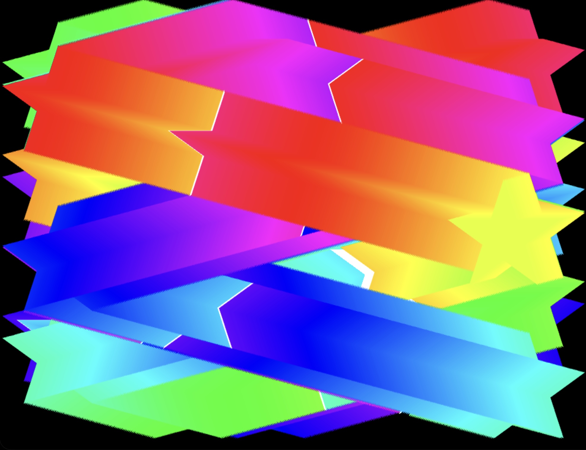
This RGB Rotary Encoder program can drive animation on the RGB Painter web page (chrome browser only). Connect the microbit to the RGB rotary encoder and keep the microbit plugged into the computer via the USB cable . Choose colors on the RGB encoder and click to fill the screen with colorful stars!
LCD Display
Displays text on the classic LCD screen (2 rows of 16 characters) found on microwaves, thermostats, and vending machines.
/*
Displays text and numbers on a 1602 LCD screen (2 rows of 16 characters).
This classic display is on microwaves, thermostats, and vending machines.
Great for showing sensor readings or status messages.

MakeCode extension required:
  In the MakeCode editor, click "Extensions"
  Search for "makecode-extensions/i2clcd1602".
  Add the extension.

Physical setup:
  The LCD module has 4 pins. It uses I2C, so it must go on specific pins:
  Connect GND → micro:bit GND
  Connect VCC → micro:bit 5V (use battery pack — LCD needs 5V for backlight)
  Connect SCL → micro:bit pin 19 (I2C clock)
  Connect SDA → micro:bit pin 20 (I2C data)

  Note: If you have a sensor shield, you can plug into one of the I2C ports.

  Tip: if the screen looks blank, adjust the blue potentiometer on the back.
*/

basic.pause(1000); // --- Setup ---
I2C_LCD1602.LcdInit(0); // Address 0 means auto-detect. Try 39 or 63 if auto doesn't work.
I2C_LCD1602.ShowString("Hello!", 0, 0); // text, column, row
I2C_LCD1602.ShowString("micro:bit", 0, 1); // text, column, row
I2C_LCD1602.BacklightOn();
I2C_LCD1602.clear();

let count = 0;

basic.forever(function () {
  // --- Main Loop ---
  // Show a counter and temperature that update every second

  I2C_LCD1602.ShowString("Count: " + count + "   ", 0, 0);
  I2C_LCD1602.ShowString("Temp: " + input.temperature() + "C ", 0, 1);
  serial.writeValue("count", count);
  count += 1;

  basic.pause(1000);
});
LCD Display Graphics
Demonstrates graphics on the classic 1602 LCD screen (2 rows of 16 characters). You can make a sort of graphics bar with characters.
/*
LCD Graphics demo - fills both rows with a dither gradient.
Button B: fill left to right (4 clicks per column, then moves to next column)
Button A: reverse/unfill

This is not very practical, but it shows how to use the LCD's custom character feature to make simple graphics.

MakeCode extension required:
In the MakeCode editor, click "Extensions"
Search for "makecode-extensions/i2clcd1602".
Add the extension.

Physical setup:
The LCD module has 4 pins. It uses I2C, so it must go on specific pins:
Connect GND → micro:bit GND
Connect VCC → micro:bit 5V (use battery pack — LCD needs 5V for backlight)
Connect SCL → micro:bit pin 19 (I2C clock)
Connect SDA → micro:bit pin 20 (I2C data)

Note: If you have a sensor shield, you can plug into one of the I2C ports.

Tip: if the screen looks blank, adjust the blue potentiometer on the back.
*/

basic.pause(1000);
I2C_LCD1602.LcdInit(0);
I2C_LCD1602.BacklightOn();
I2C_LCD1602.clear();

let topRow = "";
topRow += String.fromCharCode(127); //Left Arrow
topRow += "A------------B";
topRow += String.fromCharCode(126);
I2C_LCD1602.ShowString(topRow, 0, 0); //Top row with arrows on the sides

let fillState = 0; // how much the bottom row is filled up

function getChar(level: number): string {
  // which character should we use for each space, based on fillState
  // 16 columns × 4 steps each = 64 total steps
  // 0 = all empty, 64 = all full
  if (level <= 0) return " ";
  if (level == 1) return ":";
  if (level == 2) return "=";
  if (level == 3) return "#";
  return String.fromCharCode(255); // █ full block character
}

function drawDisplay() {
  let row = ""; // the bottom row starts empty,

  //  we build it up character by character based on fillState
  for (let col = 0; col < 16; col++) {
    let level = Math.min(4, Math.max(0, fillState - col * 4));
    row += getChar(level);
  }

  I2C_LCD1602.ShowString(row, 0, 1); // draw the bottom row based on fillState
}

input.onButtonPressed(Button.B, function () {
  if (fillState < 64) {
    fillState += 1;
    drawDisplay();
  }
});

input.onButtonPressed(Button.A, function () {
  if (fillState > 0) {
    fillState -= 1;
    drawDisplay();
  }
});
OLED Display
Displays text and numbers on a 0.96” OLED screen (128x64 pixels) —
/*
Displays text and numbers on a 0.96" oled screen (128x64 pixels).
This tiny screen gives you complex visual output.  Text, shapes, etc

MakeCode extension required:
In the MakeCode editor, click "Extensions" and search for "pythom1234/pxt-oled".

Physical setup:
  The oled module has 4 pins. It uses I2C, so it must go on specific pins:
  Connect GND → micro:bit GND
  Connect VCC → micro:bit 3V
  Connect SCL → micro:bit pin 19 (I2C clock)
  Connect SDA → micro:bit pin 20 (I2C data)

  Note: If using a shield or breakout board, there may be specific I2C ports.
*/

basic.pause(1000); // --- Setup ---
let count = 0;
oled.init();

basic.forever(function () {
  // --- Main Loop ---
  count += 1;
  // Show a counter that updates every second
  oled.clear(false);
  let text = "Count: " + count;

  oled.drawLine(0, 0, 127, 63, true, false); // top left to bottom right
  oled.drawLine(127, 0, 0, 63, true, false); //top right to bottom left
  oled.drawRect(0, 0, 127, 63, true, false, false); // screen border box
  oled.drawRect(20, 25, 100, 40, false, true, false); // black area behind text
  oled.drawText(text, 27, 27, true, false); // add some text

  oled.draw(); //nothing is shown till you call draw() — this lets you build up the screen in memory and then update it all at once, which looks smoother.

  basic.pause(1000);
});
OLED Display with Big Numbers
Displays giant styled numbers on a 0.96” OLED screen, but demonstrates a technique to encode large numbers as bitmap images
/*
Displays text and numbers on a 0.96" OLED screen (128x64 pixels).
This tiny screen gives you real visual output beyond the 5x5 LED grid —
show sensor readings, messages, or simple graphics.

MakeCode extension required:
pythom1234/pxt-oled

Physical setup:
  The OLED module has 4 pins. It uses I2C, so it must go on specific pins:
  Connect GND → micro:bit GND
  Connect VCC → micro:bit 3V
  Connect SCL → micro:bit pin 19 (I2C clock)
  Connect SDA → micro:bit pin 20 (I2C data)

  Note: If using a shield or breakout board, there may be specific I2C ports.
*/

basic.pause(1000); // --- Setup ---

// These are custom number bitmaps generated by tangible-interfaces.com/code/font_to_makecode.html
// Font: Space Mono Bold 700  |  Height: 60px. Source Google Fonts

const GLYPH_D0 = images.createImage(
  ". . . . . . . . . . . . . . . . # # # # # # # # # # . . . . . . . . . . . . . . . .\n. . . . . . . . . . . . # # # # # # # # # # # # # # # # # # . . . . . . . . . . . .\n. . . . . . . . . . # # # # # # # # # # # # # # # # # # # # # # . . . . . . . . . .\n. . . . . . . . . # # # # # # # # # # # # # # # # # # # # # # # # . . . . . . . . .\n. . . . . . . # # # # # # # # # # # # # # # # # # # # # # # # # # # # . . . . . . .\n. . . . . . # # # # # # # # # # # # # # # # # # # # # # # # # # # # # # . . . . . .\n. . . . . # # # # # # # # # # # # # # # # # # # # # # # # # # # # # # # # . . . . .\n. . . . # # # # # # # # # # # # # # # # # # # # # # # # # # # # # # # # # # . . . .\n. . . . # # # # # # # # # # # # # # # # # # # # # # # # # # # # # # # # # # . . . .\n. . . # # # # # # # # # # # # # # # # # # # # # # # # # # # # # # # # # # # # . . .\n. . # # # # # # # # # # # # # # # . . . . . . . . # # # # # # # # # # # # # # . . .\n. . # # # # # # # # # # # # # . . . . . . . . . . . . # # # # # # # # # # # # # . .\n. . # # # # # # # # # # # # . . . . . . . . . . . . . . # # # # # # # # # # # # . .\n. # # # # # # # # # # # # . . . . . . . . . . . . . . . . # # # # # # # # # # # # .\n. # # # # # # # # # # # . . . . . . . . . . . . . . . . . # # # # # # # # # # # # .\n. # # # # # # # # # # # . . . . . . . . . . . . . . . . . . # # # # # # # # # # # .\n. # # # # # # # # # # # . . . . . . . . . . . . . . . . . . # # # # # # # # # # # .\n# # # # # # # # # # # . . . . . . . . . . . . . . . . . . . . # # # # # # # # # # #\n# # # # # # # # # # # . . . . . . . . . . . . . . . . . . . . # # # # # # # # # # #\n# # # # # # # # # # # . . . . . . . . . . . . . . . . . . . . # # # # # # # # # # #\n# # # # # # # # # # # . . . . . . . . . . . . . . . . . . . . # # # # # # # # # # #\n# # # # # # # # # # # . . . . . . . . . . . . . . . . . . . . # # # # # # # # # # #\n# # # # # # # # # # # . . . . . . . . . . . . . . . . . . . . # # # # # # # # # # #\n# # # # # # # # # # # . . . . . . . # # # # # . . . . . . . . # # # # # # # # # # #\n# # # # # # # # # # # . . . . . . # # # # # # # # . . . . . . # # # # # # # # # # #\n# # # # # # # # # # # . . . . . # # # # # # # # # # . . . . . # # # # # # # # # # #\n# # # # # # # # # # # . . . . # # # # # # # # # # # # . . . . # # # # # # # # # # #\n# # # # # # # # # # # . . . . # # # # # # # # # # # # . . . . # # # # # # # # # # #\n# # # # # # # # # # # . . . # # # # # # # # # # # # # # . . . # # # # # # # # # # #\n# # # # # # # # # # # . . . # # # # # # # # # # # # # # . . . # # # # # # # # # # #\n# # # # # # # # # # # . . . # # # # # # # # # # # # # # . . . # # # # # # # # # # #\n# # # # # # # # # # # . . . # # # # # # # # # # # # # # . . . # # # # # # # # # # #\n# # # # # # # # # # # . . . . # # # # # # # # # # # # . . . . # # # # # # # # # # #\n# # # # # # # # # # # . . . . # # # # # # # # # # # # . . . . # # # # # # # # # # #\n# # # # # # # # # # # . . . . . # # # # # # # # # # . . . . . # # # # # # # # # # #\n# # # # # # # # # # # . . . . . . # # # # # # # # . . . . . . # # # # # # # # # # #\n# # # # # # # # # # # . . . . . . . . # # # # . . . . . . . . # # # # # # # # # # #\n# # # # # # # # # # # . . . . . . . . . . . . . . . . . . . . # # # # # # # # # # #\n# # # # # # # # # # # . . . . . . . . . . . . . . . . . . . . # # # # # # # # # # #\n# # # # # # # # # # # . . . . . . . . . . . . . . . . . . . . # # # # # # # # # # #\n# # # # # # # # # # # . . . . . . . . . . . . . . . . . . . . # # # # # # # # # # #\n# # # # # # # # # # # . . . . . . . . . . . . . . . . . . . . # # # # # # # # # # #\n# # # # # # # # # # # . . . . . . . . . . . . . . . . . . . . # # # # # # # # # # #\n. # # # # # # # # # # # . . . . . . . . . . . . . . . . . . # # # # # # # # # # # .\n. # # # # # # # # # # # . . . . . . . . . . . . . . . . . . # # # # # # # # # # # .\n. # # # # # # # # # # # . . . . . . . . . . . . . . . . . # # # # # # # # # # # # .\n. # # # # # # # # # # # # . . . . . . . . . . . . . . . . # # # # # # # # # # # # .\n. . # # # # # # # # # # # # . . . . . . . . . . . . . . # # # # # # # # # # # # . .\n. . # # # # # # # # # # # # # . . . . . . . . . . . . # # # # # # # # # # # # # . .\n. . # # # # # # # # # # # # # # # . . . . . . . . # # # # # # # # # # # # # # . . .\n. . . # # # # # # # # # # # # # # # # # # # # # # # # # # # # # # # # # # # # . . .\n. . . . # # # # # # # # # # # # # # # # # # # # # # # # # # # # # # # # # # . . . .\n. . . . # # # # # # # # # # # # # # # # # # # # # # # # # # # # # # # # # # . . . .\n. . . . . # # # # # # # # # # # # # # # # # # # # # # # # # # # # # # # # . . . . .\n. . . . . . # # # # # # # # # # # # # # # # # # # # # # # # # # # # # # . . . . . .\n. . . . . . . # # # # # # # # # # # # # # # # # # # # # # # # # # # # . . . . . . .\n. . . . . . . . . # # # # # # # # # # # # # # # # # # # # # # # # . . . . . . . . .\n. . . . . . . . . . # # # # # # # # # # # # # # # # # # # # # # . . . . . . . . . .\n. . . . . . . . . . . . # # # # # # # # # # # # # # # # # # . . . . . . . . . . . .\n. . . . . . . . . . . . . . . . # # # # # # # # # # . . . . . . . . . . . . . . . .",
);
const GLYPH_D1 = images.createImage(
  ". . . . . . . # # # # # # # # # # # # # # # # # # # # # # . . . . . . . . . . . . . . .\n. . . . . . . # # # # # # # # # # # # # # # # # # # # # # . . . . . . . . . . . . . . .\n. . . . . . . # # # # # # # # # # # # # # # # # # # # # # . . . . . . . . . . . . . . .\n. . . . . . # # # # # # # # # # # # # # # # # # # # # # # . . . . . . . . . . . . . . .\n. . . . . . # # # # # # # # # # # # # # # # # # # # # # # . . . . . . . . . . . . . . .\n. . . . . . # # # # # # # # # # # # # # # # # # # # # # # . . . . . . . . . . . . . . .\n. . . . . # # # # # # # # # # # . . # # # # # # # # # # # . . . . . . . . . . . . . . .\n. . . . . # # # # # # # # # # # . . # # # # # # # # # # # . . . . . . . . . . . . . . .\n. . . . . # # # # # # # # # # # . . # # # # # # # # # # # . . . . . . . . . . . . . . .\n. . . . . # # # # # # # # # # . . . # # # # # # # # # # # . . . . . . . . . . . . . . .\n. . . . # # # # # # # # # # # . . . # # # # # # # # # # # . . . . . . . . . . . . . . .\n. . . . # # # # # # # # # # # . . . # # # # # # # # # # # . . . . . . . . . . . . . . .\n. . . . # # # # # # # # # # # . . . # # # # # # # # # # # . . . . . . . . . . . . . . .\n. . . # # # # # # # # # # # . . . . # # # # # # # # # # # . . . . . . . . . . . . . . .\n. . . # # # # # # # # # # # . . . . # # # # # # # # # # # . . . . . . . . . . . . . . .\n. . . # # # # # # # # # # # . . . . # # # # # # # # # # # . . . . . . . . . . . . . . .\n. . . # # # # # # # # # # . . . . . # # # # # # # # # # # . . . . . . . . . . . . . . .\n. . # # # # # # # # # # # . . . . . # # # # # # # # # # # . . . . . . . . . . . . . . .\n. . # # # # # # # # # # # . . . . . # # # # # # # # # # # . . . . . . . . . . . . . . .\n. . # # # # # # # # # # # . . . . . # # # # # # # # # # # . . . . . . . . . . . . . . .\n. # # # # # # # # # # # . . . . . . # # # # # # # # # # # . . . . . . . . . . . . . . .\n. # # # # # # # # # # # . . . . . . # # # # # # # # # # # . . . . . . . . . . . . . . .\n. # # # # # # # # # # # . . . . . . # # # # # # # # # # # . . . . . . . . . . . . . . .\n. # # # # # # # # # # # . . . . . . # # # # # # # # # # # . . . . . . . . . . . . . . .\n# # # # # # # # # # # . . . . . . . # # # # # # # # # # # . . . . . . . . . . . . . . .\n# # # # # # # # # # # . . . . . . . # # # # # # # # # # # . . . . . . . . . . . . . . .\n. . . . . . . . . . . . . . . . . . # # # # # # # # # # # . . . . . . . . . . . . . . .\n. . . . . . . . . . . . . . . . . . # # # # # # # # # # # . . . . . . . . . . . . . . .\n. . . . . . . . . . . . . . . . . . # # # # # # # # # # # . . . . . . . . . . . . . . .\n. . . . . . . . . . . . . . . . . . # # # # # # # # # # # . . . . . . . . . . . . . . .\n. . . . . . . . . . . . . . . . . . # # # # # # # # # # # . . . . . . . . . . . . . . .\n. . . . . . . . . . . . . . . . . . # # # # # # # # # # # . . . . . . . . . . . . . . .\n. . . . . . . . . . . . . . . . . . # # # # # # # # # # # . . . . . . . . . . . . . . .\n. . . . . . . . . . . . . . . . . . # # # # # # # # # # # . . . . . . . . . . . . . . .\n. . . . . . . . . . . . . . . . . . # # # # # # # # # # # . . . . . . . . . . . . . . .\n. . . . . . . . . . . . . . . . . . # # # # # # # # # # # . . . . . . . . . . . . . . .\n. . . . . . . . . . . . . . . . . . # # # # # # # # # # # . . . . . . . . . . . . . . .\n. . . . . . . . . . . . . . . . . . # # # # # # # # # # # . . . . . . . . . . . . . . .\n. . . . . . . . . . . . . . . . . . # # # # # # # # # # # . . . . . . . . . . . . . . .\n. . . . . . . . . . . . . . . . . . # # # # # # # # # # # . . . . . . . . . . . . . . .\n. . . . . . . . . . . . . . . . . . # # # # # # # # # # # . . . . . . . . . . . . . . .\n. . . . . . . . . . . . . . . . . . # # # # # # # # # # # . . . . . . . . . . . . . . .\n. . . . . . . . . . . . . . . . . . # # # # # # # # # # # . . . . . . . . . . . . . . .\n. . . . . . . . . . . . . . . . . . # # # # # # # # # # # . . . . . . . . . . . . . . .\n. . . . . . . . . . . . . . . . . . # # # # # # # # # # # . . . . . . . . . . . . . . .\n. . . . . . . . . . . . . . . . . . # # # # # # # # # # # . . . . . . . . . . . . . . .\n. . . . . . . . . . . . . . . . . . # # # # # # # # # # # . . . . . . . . . . . . . . .\n. . . . . . . . . . . . . . . . . . # # # # # # # # # # # . . . . . . . . . . . . . . .\n. . . . . . . . . . . . . . . . . . # # # # # # # # # # # . . . . . . . . . . . . . . .\n. # # # # # # # # # # # # # # # # # # # # # # # # # # # # # # # # # # # # # # # # # # #\n. # # # # # # # # # # # # # # # # # # # # # # # # # # # # # # # # # # # # # # # # # # #\n. # # # # # # # # # # # # # # # # # # # # # # # # # # # # # # # # # # # # # # # # # # #\n. # # # # # # # # # # # # # # # # # # # # # # # # # # # # # # # # # # # # # # # # # # #\n. # # # # # # # # # # # # # # # # # # # # # # # # # # # # # # # # # # # # # # # # # # #\n. # # # # # # # # # # # # # # # # # # # # # # # # # # # # # # # # # # # # # # # # # # #\n. # # # # # # # # # # # # # # # # # # # # # # # # # # # # # # # # # # # # # # # # # # #\n. # # # # # # # # # # # # # # # # # # # # # # # # # # # # # # # # # # # # # # # # # # #\n. # # # # # # # # # # # # # # # # # # # # # # # # # # # # # # # # # # # # # # # # # # #\n. # # # # # # # # # # # # # # # # # # # # # # # # # # # # # # # # # # # # # # # # # # #\n. # # # # # # # # # # # # # # # # # # # # # # # # # # # # # # # # # # # # # # # # # # #",
);
const GLYPH_D2 = images.createImage(
  ". . . . . . . . . . . . . . . . # # # # # # # # # # # . . . . . . . . . . . . . . .\n. . . . . . . . . . . . # # # # # # # # # # # # # # # # # # . . . . . . . . . . . .\n. . . . . . . . . . # # # # # # # # # # # # # # # # # # # # # # # . . . . . . . . .\n. . . . . . . . . # # # # # # # # # # # # # # # # # # # # # # # # # . . . . . . . .\n. . . . . . . # # # # # # # # # # # # # # # # # # # # # # # # # # # # # . . . . . .\n. . . . . . # # # # # # # # # # # # # # # # # # # # # # # # # # # # # # # . . . . .\n. . . . . # # # # # # # # # # # # # # # # # # # # # # # # # # # # # # # # # . . . .\n. . . . # # # # # # # # # # # # # # # # # # # # # # # # # # # # # # # # # # . . . .\n. . . . # # # # # # # # # # # # # # # # # # # # # # # # # # # # # # # # # # # . . .\n. . . # # # # # # # # # # # # # # # # # # # # # # # # # # # # # # # # # # # # # . .\n. . # # # # # # # # # # # # # # # # # # # # # # # # # # # # # # # # # # # # # # . .\n. . # # # # # # # # # # # # # # # . . . . . . . . . # # # # # # # # # # # # # # # .\n. # # # # # # # # # # # # # # . . . . . . . . . . . . . # # # # # # # # # # # # # .\n. # # # # # # # # # # # # # . . . . . . . . . . . . . . . # # # # # # # # # # # # .\n. # # # # # # # # # # # # . . . . . . . . . . . . . . . . . # # # # # # # # # # # #\n# # # # # # # # # # # # . . . . . . . . . . . . . . . . . . # # # # # # # # # # # #\n# # # # # # # # # # # # . . . . . . . . . . . . . . . . . . . # # # # # # # # # # #\n# # # # # # # # # # # . . . . . . . . . . . . . . . . . . . . # # # # # # # # # # #\n# # # # # # # # # # # . . . . . . . . . . . . . . . . . . . . # # # # # # # # # # #\n# # # # # # # # # # # . . . . . . . . . . . . . . . . . . . . # # # # # # # # # # #\n# # # # # # # # # # # . . . . . . . . . . . . . . . . . . . . # # # # # # # # # # #\n# # # # # # # # # # # . . . . . . . . . . . . . . . . . . . . # # # # # # # # # # #\n# # # # # # # # # # # . . . . . . . . . . . . . . . . . . . # # # # # # # # # # # #\n# # # # # # # # # # # . . . . . . . . . . . . . . . . . . . # # # # # # # # # # # #\n# # # # # # # # # # # . . . . . . . . . . . . . . . . . . # # # # # # # # # # # # .\n. . . . . . . . . . . . . . . . . . . . . . . . . . . . # # # # # # # # # # # # # .\n. . . . . . . . . . . . . . . . . . . . . . . . . . # # # # # # # # # # # # # # # .\n. . . . . . . . . . . . . . . . . . . . . . . . # # # # # # # # # # # # # # # # . .\n. . . . . . . . . . . . . . . . . . . . . # # # # # # # # # # # # # # # # # # # . .\n. . . . . . . . . . . . . . . . . # # # # # # # # # # # # # # # # # # # # # # . . .\n. . . . . . . . . . . . . . # # # # # # # # # # # # # # # # # # # # # # # # # . . .\n. . . . . . . . . . . # # # # # # # # # # # # # # # # # # # # # # # # # # # . . . .\n. . . . . . . . . # # # # # # # # # # # # # # # # # # # # # # # # # # # # . . . . .\n. . . . . . . . # # # # # # # # # # # # # # # # # # # # # # # # # # # # . . . . . .\n. . . . . . # # # # # # # # # # # # # # # # # # # # # # # # # # # # . . . . . . . .\n. . . . . # # # # # # # # # # # # # # # # # # # # # # # # # # # # . . . . . . . . .\n. . . . # # # # # # # # # # # # # # # # # # # # # # # # # # # . . . . . . . . . . .\n. . . # # # # # # # # # # # # # # # # # # # # # # # # # . . . . . . . . . . . . . .\n. . . # # # # # # # # # # # # # # # # # # # # # # . . . . . . . . . . . . . . . . .\n. . # # # # # # # # # # # # # # # # # # # . . . . . . . . . . . . . . . . . . . . .\n. . # # # # # # # # # # # # # # # # . . . . . . . . . . . . . . . . . . . . . . . .\n. # # # # # # # # # # # # # # # . . . . . . . . . . . . . . . . . . . . . . . . . .\n. # # # # # # # # # # # # # . . . . . . . . . . . . . . . . . . . . . . . . . . . .\n. # # # # # # # # # # # # . . . . . . . . . . . . . . . . . . . . . . . . . . . . .\n. # # # # # # # # # # # . . . . . . . . . . . . . . . . . . . . . . . . . . . . . .\n. # # # # # # # # # # # . . . . . . . . . . . . . . . . . . . . . . . . . . . . . .\n. # # # # # # # # # # # . . . . . . . . . . . . . . . . . . . . . . . . . . . . . .\n. # # # # # # # # # # . . . . . . . . . . . . . . . . . . . . . . . . . . . . . . .\n# # # # # # # # # # # . . . . . . . . . . . . . . . . . . . . . . . . . . . . . . .\n# # # # # # # # # # # # # # # # # # # # # # # # # # # # # # # # # # # # # # # # # .\n# # # # # # # # # # # # # # # # # # # # # # # # # # # # # # # # # # # # # # # # # .\n# # # # # # # # # # # # # # # # # # # # # # # # # # # # # # # # # # # # # # # # # .\n# # # # # # # # # # # # # # # # # # # # # # # # # # # # # # # # # # # # # # # # # .\n# # # # # # # # # # # # # # # # # # # # # # # # # # # # # # # # # # # # # # # # # .\n# # # # # # # # # # # # # # # # # # # # # # # # # # # # # # # # # # # # # # # # # .\n# # # # # # # # # # # # # # # # # # # # # # # # # # # # # # # # # # # # # # # # # .\n# # # # # # # # # # # # # # # # # # # # # # # # # # # # # # # # # # # # # # # # # .\n# # # # # # # # # # # # # # # # # # # # # # # # # # # # # # # # # # # # # # # # # .\n# # # # # # # # # # # # # # # # # # # # # # # # # # # # # # # # # # # # # # # # # .\n# # # # # # # # # # # # # # # # # # # # # # # # # # # # # # # # # # # # # # # # # .",
);
const GLYPH_D3 = images.createImage(
  "# # # # # # # # # # # # # # # # # # # # # # # # # # # # # # # # # # # # # # # . . .\n# # # # # # # # # # # # # # # # # # # # # # # # # # # # # # # # # # # # # # # . . .\n# # # # # # # # # # # # # # # # # # # # # # # # # # # # # # # # # # # # # # # . . .\n# # # # # # # # # # # # # # # # # # # # # # # # # # # # # # # # # # # # # # # . . .\n# # # # # # # # # # # # # # # # # # # # # # # # # # # # # # # # # # # # # # # . . .\n# # # # # # # # # # # # # # # # # # # # # # # # # # # # # # # # # # # # # # # . . .\n# # # # # # # # # # # # # # # # # # # # # # # # # # # # # # # # # # # # # # # . . .\n# # # # # # # # # # # # # # # # # # # # # # # # # # # # # # # # # # # # # # # . . .\n# # # # # # # # # # # # # # # # # # # # # # # # # # # # # # # # # # # # # # # . . .\n# # # # # # # # # # # # # # # # # # # # # # # # # # # # # # # # # # # # # # # . . .\n# # # # # # # # # # # # # # # # # # # # # # # # # # # # # # # # # # # # # # # . . .\n. . . . . . . . . . . . . . . . . . . . . . . . . . . . . . # # # # # # # # # . . .\n. . . . . . . . . . . . . . . . . . . . . . . . . . . . # # # # # # # # # # # . . .\n. . . . . . . . . . . . . . . . . . . . . . . . # # # # # # # # # # # # # # # . . .\n. . . . . . . . . . . . . . . . . . . . . # # # # # # # # # # # # # # # # # # . . .\n. . . . . . . . . . . . . . . . . # # # # # # # # # # # # # # # # # # # # # # . . .\n. . . . . . . . . . . . . . . # # # # # # # # # # # # # # # # # # # # # # # # . . .\n. . . . . . . . . . . . . . . # # # # # # # # # # # # # # # # # # # # # # # # . . .\n. . . . . . . . . . . . . . . # # # # # # # # # # # # # # # # # # # # # # # # . . .\n. . . . . . . . . . . . . . . # # # # # # # # # # # # # # # # # # # # . . . . . . .\n. . . . . . . . . . . . . . . # # # # # # # # # # # # # # # # # . . . . . . . . . .\n. . . . . . . . . . . . . . . # # # # # # # # # # # # # . . . . . . . . . . . . . .\n. . . . . . . . . . . . . . . # # # # # # # # # # . . . . . . . . . . . . . . . . .\n. . . . . . . . . . . . . . . # # # # # # # # . . . . . . . . . . . . . . . . . . .\n. . . . . . . . . . . . . . . # # # # # # # # . . . . . . . . . . . . . . . . . . .\n. . . . . . . . . . . . . . . # # # # # # # # # # # # # # # # . . . . . . . . . . .\n. . . . . . . . . . . . . . . # # # # # # # # # # # # # # # # # # # . . . . . . . .\n. . . . . . . . . . . . . . . # # # # # # # # # # # # # # # # # # # # . . . . . . .\n. . . . . . . . . . . . . . . # # # # # # # # # # # # # # # # # # # # # # . . . . .\n. . . . . . . . . . . . . . . # # # # # # # # # # # # # # # # # # # # # # # . . . .\n. . . . . . . . . . . . . . . # # # # # # # # # # # # # # # # # # # # # # # # . . .\n. . . . . . . . . . . . . . . # # # # # # # # # # # # # # # # # # # # # # # # . . .\n. . . . . . . . . . . . . . . # # # # # # # # # # # # # # # # # # # # # # # # # . .\n. . . . . . . . . . . . . . . # # # # # # # # # # # # # # # # # # # # # # # # # # .\n. . . . . . . . . . . . . . . . . . . . . . . . . . # # # # # # # # # # # # # # # .\n. . . . . . . . . . . . . . . . . . . . . . . . . . . . # # # # # # # # # # # # # .\n# # # # # # # # # # # . . . . . . . . . . . . . . . . . . # # # # # # # # # # # # .\n# # # # # # # # # # # . . . . . . . . . . . . . . . . . . . # # # # # # # # # # # #\n# # # # # # # # # # # . . . . . . . . . . . . . . . . . . . # # # # # # # # # # # #\n# # # # # # # # # # # . . . . . . . . . . . . . . . . . . . . # # # # # # # # # # #\n# # # # # # # # # # # . . . . . . . . . . . . . . . . . . . . # # # # # # # # # # #\n# # # # # # # # # # # . . . . . . . . . . . . . . . . . . . . # # # # # # # # # # #\n# # # # # # # # # # # # . . . . . . . . . . . . . . . . . . . # # # # # # # # # # #\n# # # # # # # # # # # # . . . . . . . . . . . . . . . . . . # # # # # # # # # # # #\n# # # # # # # # # # # # . . . . . . . . . . . . . . . . . . # # # # # # # # # # # #\n. # # # # # # # # # # # # . . . . . . . . . . . . . . . . . # # # # # # # # # # # #\n. # # # # # # # # # # # # # . . . . . . . . . . . . . . . # # # # # # # # # # # # .\n. # # # # # # # # # # # # # # . . . . . . . . . . . . . # # # # # # # # # # # # # .\n. . # # # # # # # # # # # # # # . . . . . . . . . . # # # # # # # # # # # # # # # .\n. . # # # # # # # # # # # # # # # # # # # # # # # # # # # # # # # # # # # # # # . .\n. . . # # # # # # # # # # # # # # # # # # # # # # # # # # # # # # # # # # # # # . .\n. . . . # # # # # # # # # # # # # # # # # # # # # # # # # # # # # # # # # # # . . .\n. . . . # # # # # # # # # # # # # # # # # # # # # # # # # # # # # # # # # # # . . .\n. . . . . # # # # # # # # # # # # # # # # # # # # # # # # # # # # # # # # # . . . .\n. . . . . . # # # # # # # # # # # # # # # # # # # # # # # # # # # # # # # . . . . .\n. . . . . . . # # # # # # # # # # # # # # # # # # # # # # # # # # # # # . . . . . .\n. . . . . . . . . # # # # # # # # # # # # # # # # # # # # # # # # # # . . . . . . .\n. . . . . . . . . . . # # # # # # # # # # # # # # # # # # # # # # . . . . . . . . .\n. . . . . . . . . . . . . # # # # # # # # # # # # # # # # # # . . . . . . . . . . .\n. . . . . . . . . . . . . . . . . # # # # # # # # # # . . . . . . . . . . . . . . .",
);
const GLYPH_D4 = images.createImage(
  ". . . . . . . . . . . . . . . . # # # # # # # # # # # # # # # # # # # # # # . . . . . . . . .\n. . . . . . . . . . . . . . . . # # # # # # # # # # # # # # # # # # # # # # . . . . . . . . .\n. . . . . . . . . . . . . . . # # # # # # # # # # # # # # # # # # # # # # # . . . . . . . . .\n. . . . . . . . . . . . . . . # # # # # # # # # # # # # # # # # # # # # # # . . . . . . . . .\n. . . . . . . . . . . . . . # # # # # # # # # # # # # # # # # # # # # # # # . . . . . . . . .\n. . . . . . . . . . . . . . # # # # # # # # # # # # # # # # # # # # # # # # . . . . . . . . .\n. . . . . . . . . . . . . # # # # # # # # # # # # . . # # # # # # # # # # # . . . . . . . . .\n. . . . . . . . . . . . . # # # # # # # # # # # . . . # # # # # # # # # # # . . . . . . . . .\n. . . . . . . . . . . . # # # # # # # # # # # # . . . # # # # # # # # # # # . . . . . . . . .\n. . . . . . . . . . . . # # # # # # # # # # # . . . . # # # # # # # # # # # . . . . . . . . .\n. . . . . . . . . . . # # # # # # # # # # # # . . . . # # # # # # # # # # # . . . . . . . . .\n. . . . . . . . . . . # # # # # # # # # # # . . . . . # # # # # # # # # # # . . . . . . . . .\n. . . . . . . . . . # # # # # # # # # # # # . . . . . # # # # # # # # # # # . . . . . . . . .\n. . . . . . . . . . # # # # # # # # # # # . . . . . . # # # # # # # # # # # . . . . . . . . .\n. . . . . . . . . # # # # # # # # # # # # . . . . . . # # # # # # # # # # # . . . . . . . . .\n. . . . . . . . . # # # # # # # # # # # . . . . . . . # # # # # # # # # # # . . . . . . . . .\n. . . . . . . . # # # # # # # # # # # # . . . . . . . # # # # # # # # # # # . . . . . . . . .\n. . . . . . . . # # # # # # # # # # # . . . . . . . . # # # # # # # # # # # . . . . . . . . .\n. . . . . . . # # # # # # # # # # # # . . . . . . . . # # # # # # # # # # # . . . . . . . . .\n. . . . . . . # # # # # # # # # # # . . . . . . . . . # # # # # # # # # # # . . . . . . . . .\n. . . . . . # # # # # # # # # # # # . . . . . . . . . # # # # # # # # # # # . . . . . . . . .\n. . . . . . # # # # # # # # # # # . . . . . . . . . . # # # # # # # # # # # . . . . . . . . .\n. . . . . # # # # # # # # # # # # . . . . . . . . . . # # # # # # # # # # # . . . . . . . . .\n. . . . . # # # # # # # # # # # . . . . . . . . . . . # # # # # # # # # # # . . . . . . . . .\n. . . . # # # # # # # # # # # # . . . . . . . . . . . # # # # # # # # # # # . . . . . . . . .\n. . . . # # # # # # # # # # # . . . . . . . . . . . . # # # # # # # # # # # . . . . . . . . .\n. . . # # # # # # # # # # # # . . . . . . . . . . . . # # # # # # # # # # # . . . . . . . . .\n. . . # # # # # # # # # # # . . . . . . . . . . . . . # # # # # # # # # # # . . . . . . . . .\n. . # # # # # # # # # # # # . . . . . . . . . . . . . # # # # # # # # # # # . . . . . . . . .\n. . # # # # # # # # # # # . . . . . . . . . . . . . . # # # # # # # # # # # . . . . . . . . .\n. # # # # # # # # # # # # . . . . . . . . . . . . . . # # # # # # # # # # # . . . . . . . . .\n. # # # # # # # # # # # . . . . . . . . . . . . . . . # # # # # # # # # # # . . . . . . . . .\n# # # # # # # # # # # # . . . . . . . . . . . . . . . # # # # # # # # # # # . . . . . . . . .\n# # # # # # # # # # # . . . . . . . . . . . . . . . . # # # # # # # # # # # . . . . . . . . .\n# # # # # # # # # # # . . . . . . . . . . . . . . . . # # # # # # # # # # # . . . . . . . . .\n# # # # # # # # # # . . . . . . . . . . . . . . . . . # # # # # # # # # # # . . . . . . . . .\n# # # # # # # # # # . . . . . . . . . . . . . . . . . # # # # # # # # # # # . . . . . . . . .\n# # # # # # # # # # . . . . . . . . . . . . . . . . . # # # # # # # # # # # . . . . . . . . .\n# # # # # # # # # # # # # # # # # # # # # # # # # # # # # # # # # # # # # # # # # # # # # # #\n# # # # # # # # # # # # # # # # # # # # # # # # # # # # # # # # # # # # # # # # # # # # # # #\n# # # # # # # # # # # # # # # # # # # # # # # # # # # # # # # # # # # # # # # # # # # # # # #\n# # # # # # # # # # # # # # # # # # # # # # # # # # # # # # # # # # # # # # # # # # # # # # #\n# # # # # # # # # # # # # # # # # # # # # # # # # # # # # # # # # # # # # # # # # # # # # # #\n# # # # # # # # # # # # # # # # # # # # # # # # # # # # # # # # # # # # # # # # # # # # # # #\n# # # # # # # # # # # # # # # # # # # # # # # # # # # # # # # # # # # # # # # # # # # # # # #\n# # # # # # # # # # # # # # # # # # # # # # # # # # # # # # # # # # # # # # # # # # # # # # #\n# # # # # # # # # # # # # # # # # # # # # # # # # # # # # # # # # # # # # # # # # # # # # # #\n# # # # # # # # # # # # # # # # # # # # # # # # # # # # # # # # # # # # # # # # # # # # # # #\n# # # # # # # # # # # # # # # # # # # # # # # # # # # # # # # # # # # # # # # # # # # # # # #\n. . . . . . . . . . . . . . . . . . . . . . . . . . . # # # # # # # # # # # . . . . . . . . .\n. . . . . . . . . . . . . . . . . . . . . . . . . . . # # # # # # # # # # # . . . . . . . . .\n. . . . . . . . . . . . . . . . . . . . . . . . . . . # # # # # # # # # # # . . . . . . . . .\n. . . . . . . . . . . . . . . . . . . . . . . . . . . # # # # # # # # # # # . . . . . . . . .\n. . . . . . . . . . . . . . . . . . . . . . . . . . . # # # # # # # # # # # . . . . . . . . .\n. . . . . . . . . . . . . . . . . . . . . . . . . . . # # # # # # # # # # # . . . . . . . . .\n. . . . . . . . . . . . . . . . . . . . . . . . . . . # # # # # # # # # # # . . . . . . . . .\n. . . . . . . . . . . . . . . . . . . . . . . . . . . # # # # # # # # # # # . . . . . . . . .\n. . . . . . . . . . . . . . . . . . . . . . . . . . . # # # # # # # # # # # . . . . . . . . .\n. . . . . . . . . . . . . . . . . . . . . . . . . . . # # # # # # # # # # # . . . . . . . . .\n. . . . . . . . . . . . . . . . . . . . . . . . . . . # # # # # # # # # # # . . . . . . . . .",
);
const GLYPH_D5 = images.createImage(
  ". # # # # # # # # # # # # # # # # # # # # # # # # # # # # # # # # # # # # # # # . . . .\n. # # # # # # # # # # # # # # # # # # # # # # # # # # # # # # # # # # # # # # # . . . .\n. # # # # # # # # # # # # # # # # # # # # # # # # # # # # # # # # # # # # # # # . . . .\n. # # # # # # # # # # # # # # # # # # # # # # # # # # # # # # # # # # # # # # # . . . .\n. # # # # # # # # # # # # # # # # # # # # # # # # # # # # # # # # # # # # # # # . . . .\n. # # # # # # # # # # # # # # # # # # # # # # # # # # # # # # # # # # # # # # # . . . .\n. # # # # # # # # # # # # # # # # # # # # # # # # # # # # # # # # # # # # # # # . . . .\n. # # # # # # # # # # # # # # # # # # # # # # # # # # # # # # # # # # # # # # # . . . .\n. # # # # # # # # # # # # # # # # # # # # # # # # # # # # # # # # # # # # # # # . . . .\n. # # # # # # # # # # # # # # # # # # # # # # # # # # # # # # # # # # # # # # # . . . .\n. # # # # # # # # # # # # # # # # # # # # # # # # # # # # # # # # # # # # # # # . . . .\n. # # # # # # # # # # # . . . . . . . . . . . . . . . . . . . . . . . . . . . . . . . .\n. # # # # # # # # # # # . . . . . . . . . . . . . . . . . . . . . . . . . . . . . . . .\n. # # # # # # # # # # # . . . . . . . . . . . . . . . . . . . . . . . . . . . . . . . .\n. # # # # # # # # # # # . . . . . . . . . . . . . . . . . . . . . . . . . . . . . . . .\n. # # # # # # # # # # # . . . . . . . . . . . . . . . . . . . . . . . . . . . . . . . .\n. # # # # # # # # # # # . . . . . . . . . . . . . . . . . . . . . . . . . . . . . . . .\n. # # # # # # # # # # # . . . . . . . . . . . . . . . . . . . . . . . . . . . . . . . .\n. # # # # # # # # # # # . . . . . . . . . . . . . . . . . . . . . . . . . . . . . . . .\n. # # # # # # # # # # # . . . . . . . . . # # # # # # # # # # # # . . . . . . . . . . .\n. # # # # # # # # # # # . . . . . . . # # # # # # # # # # # # # # # # . . . . . . . . .\n. # # # # # # # # # # # . . . . . # # # # # # # # # # # # # # # # # # # # . . . . . . .\n. # # # # # # # # # # # . . . . # # # # # # # # # # # # # # # # # # # # # # . . . . . .\n. # # # # # # # # # # # . . . # # # # # # # # # # # # # # # # # # # # # # # # . . . . .\n. # # # # # # # # # # # . . . # # # # # # # # # # # # # # # # # # # # # # # # # . . . .\n. # # # # # # # # # # # . . # # # # # # # # # # # # # # # # # # # # # # # # # # # . . .\n. # # # # # # # # # # # . . # # # # # # # # # # # # # # # # # # # # # # # # # # # . . .\n. # # # # # # # # # # # # # # # # # # # # # # # # # # # # # # # # # # # # # # # # # . .\n. # # # # # # # # # # # # # # # # # # # # # # # # # # # # # # # # # # # # # # # # # . .\n. # # # # # # # # # # # # # # # # # # # # # . . . . . . # # # # # # # # # # # # # # # .\n. # # # # # # # # # # # # # # # # # # # # . . . . . . . . . # # # # # # # # # # # # # .\n. # # # # # # # # # # # # # # # # # # # . . . . . . . . . . . # # # # # # # # # # # # .\n. # # # # # # # # # # # # # # # # # # . . . . . . . . . . . . . # # # # # # # # # # # #\n. . . . . . . . . . . . . . . . . . . . . . . . . . . . . . . . # # # # # # # # # # # #\n. . . . . . . . . . . . . . . . . . . . . . . . . . . . . . . . . # # # # # # # # # # #\n. . . . . . . . . . . . . . . . . . . . . . . . . . . . . . . . . # # # # # # # # # # #\n. . . . . . . . . . . . . . . . . . . . . . . . . . . . . . . . . # # # # # # # # # # #\n. . . . . . . . . . . . . . . . . . . . . . . . . . . . . . . . . # # # # # # # # # # #\n# # # # # # # # # # # . . . . . . . . . . . . . . . . . . . . . . # # # # # # # # # # #\n# # # # # # # # # # # . . . . . . . . . . . . . . . . . . . . . . # # # # # # # # # # #\n# # # # # # # # # # # . . . . . . . . . . . . . . . . . . . . . . # # # # # # # # # # #\n# # # # # # # # # # # . . . . . . . . . . . . . . . . . . . . . . # # # # # # # # # # #\n# # # # # # # # # # # # . . . . . . . . . . . . . . . . . . . . . # # # # # # # # # # #\n# # # # # # # # # # # # . . . . . . . . . . . . . . . . . . . . # # # # # # # # # # # #\n. # # # # # # # # # # # . . . . . . . . . . . . . . . . . . . . # # # # # # # # # # # .\n. # # # # # # # # # # # # . . . . . . . . . . . . . . . . . . # # # # # # # # # # # # .\n. # # # # # # # # # # # # # . . . . . . . . . . . . . . . . # # # # # # # # # # # # # .\n. # # # # # # # # # # # # # # . . . . . . . . . . . . . . # # # # # # # # # # # # # . .\n. . # # # # # # # # # # # # # # # . . . . . . . . . . # # # # # # # # # # # # # # # . .\n. . # # # # # # # # # # # # # # # # # # # # # # # # # # # # # # # # # # # # # # # . . .\n. . . # # # # # # # # # # # # # # # # # # # # # # # # # # # # # # # # # # # # # # . . .\n. . . # # # # # # # # # # # # # # # # # # # # # # # # # # # # # # # # # # # # # . . . .\n. . . . # # # # # # # # # # # # # # # # # # # # # # # # # # # # # # # # # # # . . . . .\n. . . . . # # # # # # # # # # # # # # # # # # # # # # # # # # # # # # # # # . . . . . .\n. . . . . . # # # # # # # # # # # # # # # # # # # # # # # # # # # # # # # . . . . . . .\n. . . . . . . # # # # # # # # # # # # # # # # # # # # # # # # # # # # # . . . . . . . .\n. . . . . . . . # # # # # # # # # # # # # # # # # # # # # # # # # # # . . . . . . . . .\n. . . . . . . . . . # # # # # # # # # # # # # # # # # # # # # # # . . . . . . . . . . .\n. . . . . . . . . . . . # # # # # # # # # # # # # # # # # # # . . . . . . . . . . . . .\n. . . . . . . . . . . . . . . . # # # # # # # # # # # . . . . . . . . . . . . . . . . .",
);
const GLYPH_D6 = images.createImage(
  ". . . . . . . . . . . . . . . . # # # # # # # # # # . . . . . . . . . . . . . . .\n. . . . . . . . . . . . # # # # # # # # # # # # # # # # # . . . . . . . . . . . .\n. . . . . . . . . . # # # # # # # # # # # # # # # # # # # # # . . . . . . . . . .\n. . . . . . . . # # # # # # # # # # # # # # # # # # # # # # # # # . . . . . . . .\n. . . . . . . # # # # # # # # # # # # # # # # # # # # # # # # # # # . . . . . . .\n. . . . . . # # # # # # # # # # # # # # # # # # # # # # # # # # # # # . . . . . .\n. . . . . # # # # # # # # # # # # # # # # # # # # # # # # # # # # # # # . . . . .\n. . . . # # # # # # # # # # # # # # # # # # # # # # # # # # # # # # # # # . . . .\n. . . # # # # # # # # # # # # # # # # # # # # # # # # # # # # # # # # # # # . . .\n. . . # # # # # # # # # # # # # # # # # # # # # # # # # # # # # # # # # # # . . .\n. . # # # # # # # # # # # # # # # # . . . . . # # # # # # # # # # # # # # # # . .\n. . # # # # # # # # # # # # # # . . . . . . . . . . # # # # # # # # # # # # # . .\n. # # # # # # # # # # # # # . . . . . . . . . . . . . # # # # # # # # # # # # # .\n. # # # # # # # # # # # # . . . . . . . . . . . . . . . # # # # # # # # # # # # .\n. # # # # # # # # # # # . . . . . . . . . . . . . . . . . # # # # # # # # # # # .\n. # # # # # # # # # # # . . . . . . . . . . . . . . . . . # # # # # # # # # # # .\n# # # # # # # # # # # . . . . . . . . . . . . . . . . . . # # # # # # # # # # # .\n# # # # # # # # # # # . . . . . . . . . . . . . . . . . . . . . . . . . . . . . .\n# # # # # # # # # # # . . . . . . . . . . . . . . . . . . . . . . . . . . . . . .\n# # # # # # # # # # # . . . . . . . . . . . . . . . . . . . . . . . . . . . . . .\n# # # # # # # # # # # . . . . . . . . . . . . . . . . . . . . . . . . . . . . . .\n# # # # # # # # # # # . . . . . . . . # # # # # # # # # # . . . . . . . . . . . .\n# # # # # # # # # # # . . . . . . # # # # # # # # # # # # # # # . . . . . . . . .\n# # # # # # # # # # # . . . . # # # # # # # # # # # # # # # # # # # . . . . . . .\n# # # # # # # # # # # . . . # # # # # # # # # # # # # # # # # # # # # . . . . . .\n# # # # # # # # # # # . . # # # # # # # # # # # # # # # # # # # # # # # . . . . .\n# # # # # # # # # # # . . # # # # # # # # # # # # # # # # # # # # # # # # . . . .\n# # # # # # # # # # # # # # # # # # # # # # # # # # # # # # # # # # # # # # . . .\n# # # # # # # # # # # # # # # # # # # # # # # # # # # # # # # # # # # # # # . . .\n# # # # # # # # # # # # # # # # # # # # # # # # # # # # # # # # # # # # # # # . .\n# # # # # # # # # # # # # # # # # # # # # # # # # # # # # # # # # # # # # # # . .\n# # # # # # # # # # # # # # # # # # . . . . . . # # # # # # # # # # # # # # # # .\n# # # # # # # # # # # # # # # . . . . . . . . . . . # # # # # # # # # # # # # # .\n# # # # # # # # # # # # # # . . . . . . . . . . . . . # # # # # # # # # # # # # .\n# # # # # # # # # # # # # . . . . . . . . . . . . . . . # # # # # # # # # # # # #\n# # # # # # # # # # # # . . . . . . . . . . . . . . . . . # # # # # # # # # # # #\n# # # # # # # # # # # # . . . . . . . . . . . . . . . . . . # # # # # # # # # # #\n# # # # # # # # # # # . . . . . . . . . . . . . . . . . . . # # # # # # # # # # #\n# # # # # # # # # # # . . . . . . . . . . . . . . . . . . . # # # # # # # # # # #\n# # # # # # # # # # # . . . . . . . . . . . . . . . . . . . # # # # # # # # # # #\n# # # # # # # # # # # . . . . . . . . . . . . . . . . . . . # # # # # # # # # # #\n# # # # # # # # # # # . . . . . . . . . . . . . . . . . . . # # # # # # # # # # #\n# # # # # # # # # # # . . . . . . . . . . . . . . . . . . . # # # # # # # # # # #\n# # # # # # # # # # # . . . . . . . . . . . . . . . . . . . # # # # # # # # # # #\n# # # # # # # # # # # # . . . . . . . . . . . . . . . . . # # # # # # # # # # # #\n. # # # # # # # # # # # . . . . . . . . . . . . . . . . . # # # # # # # # # # # #\n. # # # # # # # # # # # # . . . . . . . . . . . . . . . # # # # # # # # # # # # .\n. # # # # # # # # # # # # # . . . . . . . . . . . . . # # # # # # # # # # # # # .\n. . # # # # # # # # # # # # # # . . . . . . . . . # # # # # # # # # # # # # # # .\n. . # # # # # # # # # # # # # # # # # . . . # # # # # # # # # # # # # # # # # . .\n. . . # # # # # # # # # # # # # # # # # # # # # # # # # # # # # # # # # # # # . .\n. . . # # # # # # # # # # # # # # # # # # # # # # # # # # # # # # # # # # # . . .\n. . . . # # # # # # # # # # # # # # # # # # # # # # # # # # # # # # # # # . . . .\n. . . . . # # # # # # # # # # # # # # # # # # # # # # # # # # # # # # # . . . . .\n. . . . . . # # # # # # # # # # # # # # # # # # # # # # # # # # # # # . . . . . .\n. . . . . . . # # # # # # # # # # # # # # # # # # # # # # # # # # # . . . . . . .\n. . . . . . . . # # # # # # # # # # # # # # # # # # # # # # # # # . . . . . . . .\n. . . . . . . . . . # # # # # # # # # # # # # # # # # # # # # . . . . . . . . . .\n. . . . . . . . . . . . # # # # # # # # # # # # # # # # # . . . . . . . . . . . .\n. . . . . . . . . . . . . . . . # # # # # # # # # . . . . . . . . . . . . . . . .",
);
const GLYPH_D7 = images.createImage(
  "# # # # # # # # # # # # # # # # # # # # # # # # # # # # # # # # # # # # # # # # # #\n# # # # # # # # # # # # # # # # # # # # # # # # # # # # # # # # # # # # # # # # # #\n# # # # # # # # # # # # # # # # # # # # # # # # # # # # # # # # # # # # # # # # # #\n# # # # # # # # # # # # # # # # # # # # # # # # # # # # # # # # # # # # # # # # # #\n# # # # # # # # # # # # # # # # # # # # # # # # # # # # # # # # # # # # # # # # # #\n# # # # # # # # # # # # # # # # # # # # # # # # # # # # # # # # # # # # # # # # # #\n# # # # # # # # # # # # # # # # # # # # # # # # # # # # # # # # # # # # # # # # # #\n# # # # # # # # # # # # # # # # # # # # # # # # # # # # # # # # # # # # # # # # # #\n# # # # # # # # # # # # # # # # # # # # # # # # # # # # # # # # # # # # # # # # # #\n# # # # # # # # # # # # # # # # # # # # # # # # # # # # # # # # # # # # # # # # # #\n# # # # # # # # # # # # # # # # # # # # # # # # # # # # # # # # # # # # # # # # # #\n. . . . . . . . . . . . . . . . . . . . . . . . . . . . . . . . # # # # # # # # # #\n. . . . . . . . . . . . . . . . . . . . . . . . . . . . . . . . # # # # # # # # # #\n. . . . . . . . . . . . . . . . . . . . . . . . . . . . . . . # # # # # # # # # # #\n. . . . . . . . . . . . . . . . . . . . . . . . . . . . . . # # # # # # # # # # # #\n. . . . . . . . . . . . . . . . . . . . . . . . . . . . . . # # # # # # # # # # # #\n. . . . . . . . . . . . . . . . . . . . . . . . . . . . . # # # # # # # # # # # # #\n. . . . . . . . . . . . . . . . . . . . . . . . . . . . # # # # # # # # # # # # # #\n. . . . . . . . . . . . . . . . . . . . . . . . . . . . # # # # # # # # # # # # # #\n. . . . . . . . . . . . . . . . . . . . . . . . . . . # # # # # # # # # # # # # # .\n. . . . . . . . . . . . . . . . . . . . . . . . . . # # # # # # # # # # # # # # . .\n. . . . . . . . . . . . . . . . . . . . . . . . . . # # # # # # # # # # # # # # . .\n. . . . . . . . . . . . . . . . . . . . . . . . . # # # # # # # # # # # # # # . . .\n. . . . . . . . . . . . . . . . . . . . . . . . # # # # # # # # # # # # # # . . . .\n. . . . . . . . . . . . . . . . . . . . . . . . # # # # # # # # # # # # # . . . . .\n. . . . . . . . . . . . . . . . . . . . . . . # # # # # # # # # # # # # # . . . . .\n. . . . . . . . . . . . . . . . . . . . . . # # # # # # # # # # # # # # . . . . . .\n. . . . . . . . . . . . . . . . . . . . . # # # # # # # # # # # # # # . . . . . . .\n. . . . . . . . . . . . . . . . . . . . . # # # # # # # # # # # # # # . . . . . . .\n. . . . . . . . . . . . . . . . . . . . # # # # # # # # # # # # # # . . . . . . . .\n. . . . . . . . . . . . . . . . . . . . # # # # # # # # # # # # # . . . . . . . . .\n. . . . . . . . . . . . . . . . . . . # # # # # # # # # # # # # # . . . . . . . . .\n. . . . . . . . . . . . . . . . . . # # # # # # # # # # # # # # . . . . . . . . . .\n. . . . . . . . . . . . . . . . . # # # # # # # # # # # # # # . . . . . . . . . . .\n. . . . . . . . . . . . . . . . . # # # # # # # # # # # # # # . . . . . . . . . . .\n. . . . . . . . . . . . . . . . # # # # # # # # # # # # # # . . . . . . . . . . . .\n. . . . . . . . . . . . . . . # # # # # # # # # # # # # # . . . . . . . . . . . . .\n. . . . . . . . . . . . . . . # # # # # # # # # # # # # # . . . . . . . . . . . . .\n. . . . . . . . . . . . . . # # # # # # # # # # # # # # . . . . . . . . . . . . . .\n. . . . . . . . . . . . . # # # # # # # # # # # # # # . . . . . . . . . . . . . . .\n. . . . . . . . . . . . . # # # # # # # # # # # # # # . . . . . . . . . . . . . . .\n. . . . . . . . . . . . # # # # # # # # # # # # # # . . . . . . . . . . . . . . . .\n. . . . . . . . . . . # # # # # # # # # # # # # # . . . . . . . . . . . . . . . . .\n. . . . . . . . . . . # # # # # # # # # # # # # . . . . . . . . . . . . . . . . . .\n. . . . . . . . . . # # # # # # # # # # # # # # . . . . . . . . . . . . . . . . . .\n. . . . . . . . . # # # # # # # # # # # # # # . . . . . . . . . . . . . . . . . . .\n. . . . . . . . . # # # # # # # # # # # # # . . . . . . . . . . . . . . . . . . . .\n. . . . . . . . # # # # # # # # # # # # # # . . . . . . . . . . . . . . . . . . . .\n. . . . . . . # # # # # # # # # # # # # # . . . . . . . . . . . . . . . . . . . . .\n. . . . . . . # # # # # # # # # # # # # . . . . . . . . . . . . . . . . . . . . . .\n. . . . . . # # # # # # # # # # # # # # . . . . . . . . . . . . . . . . . . . . . .\n. . . . . . # # # # # # # # # # # # # . . . . . . . . . . . . . . . . . . . . . . .\n. . . . . # # # # # # # # # # # # # # . . . . . . . . . . . . . . . . . . . . . . .\n. . . . . # # # # # # # # # # # # # . . . . . . . . . . . . . . . . . . . . . . . .\n. . . . . # # # # # # # # # # # # # . . . . . . . . . . . . . . . . . . . . . . . .\n. . . . . # # # # # # # # # # # # . . . . . . . . . . . . . . . . . . . . . . . . .\n. . . . . # # # # # # # # # # # # . . . . . . . . . . . . . . . . . . . . . . . . .\n. . . . . # # # # # # # # # # # # . . . . . . . . . . . . . . . . . . . . . . . . .\n. . . . . # # # # # # # # # # # # . . . . . . . . . . . . . . . . . . . . . . . . .\n. . . . . # # # # # # # # # # # # . . . . . . . . . . . . . . . . . . . . . . . . .",
);
const GLYPH_D8 = images.createImage(
  ". . . . . . . . . . . . . . . . # # # # # # # # # # . . . . . . . . . . . . . . . .\n. . . . . . . . . . . . # # # # # # # # # # # # # # # # # # . . . . . . . . . . . .\n. . . . . . . . . . # # # # # # # # # # # # # # # # # # # # # # . . . . . . . . . .\n. . . . . . . . # # # # # # # # # # # # # # # # # # # # # # # # # # . . . . . . . .\n. . . . . . . # # # # # # # # # # # # # # # # # # # # # # # # # # # # . . . . . . .\n. . . . . . # # # # # # # # # # # # # # # # # # # # # # # # # # # # # # # . . . . .\n. . . . . # # # # # # # # # # # # # # # # # # # # # # # # # # # # # # # # # . . . .\n. . . . # # # # # # # # # # # # # # # # # # # # # # # # # # # # # # # # # # . . . .\n. . . # # # # # # # # # # # # # # # # # # # # # # # # # # # # # # # # # # # # . . .\n. . . # # # # # # # # # # # # # # # # # # # # # # # # # # # # # # # # # # # # . . .\n. . # # # # # # # # # # # # # # # # # . . . . # # # # # # # # # # # # # # # # # . .\n. . # # # # # # # # # # # # # # . . . . . . . . . . # # # # # # # # # # # # # # . .\n. . # # # # # # # # # # # # # . . . . . . . . . . . . . # # # # # # # # # # # # . .\n. . # # # # # # # # # # # # . . . . . . . . . . . . . . . # # # # # # # # # # # . .\n. . # # # # # # # # # # # . . . . . . . . . . . . . . . . # # # # # # # # # # # # .\n. . # # # # # # # # # # # . . . . . . . . . . . . . . . . . # # # # # # # # # # # .\n. . # # # # # # # # # # . . . . . . . . . . . . . . . . . . # # # # # # # # # # # .\n. . # # # # # # # # # # . . . . . . . . . . . . . . . . . . # # # # # # # # # # . .\n. . # # # # # # # # # # # . . . . . . . . . . . . . . . . . # # # # # # # # # # . .\n. . # # # # # # # # # # # . . . . . . . . . . . . . . . . # # # # # # # # # # # . .\n. . # # # # # # # # # # # # . . . . . . . . . . . . . . . # # # # # # # # # # # . .\n. . . # # # # # # # # # # # # . . . . . . . . . . . . . # # # # # # # # # # # . . .\n. . . # # # # # # # # # # # # # . . . . . . . . . . # # # # # # # # # # # # # . . .\n. . . . # # # # # # # # # # # # # # # . . . . # # # # # # # # # # # # # # # . . . .\n. . . . . # # # # # # # # # # # # # # # # # # # # # # # # # # # # # # # # . . . . .\n. . . . . . # # # # # # # # # # # # # # # # # # # # # # # # # # # # # # . . . . . .\n. . . . . . . # # # # # # # # # # # # # # # # # # # # # # # # # # # # . . . . . . .\n. . . . . . . . . # # # # # # # # # # # # # # # # # # # # # # # # . . . . . . . . .\n. . . . . . . . . . # # # # # # # # # # # # # # # # # # # # # # . . . . . . . . . .\n. . . . . . . . . . # # # # # # # # # # # # # # # # # # # # # # . . . . . . . . . .\n. . . . . . . . # # # # # # # # # # # # # # # # # # # # # # # # # # . . . . . . . .\n. . . . . . # # # # # # # # # # # # # # # # # # # # # # # # # # # # # # . . . . . .\n. . . . . # # # # # # # # # # # # # # # # # # # # # # # # # # # # # # # # . . . . .\n. . . . # # # # # # # # # # # # # # # # # # # # # # # # # # # # # # # # # # . . . .\n. . . # # # # # # # # # # # # # # . . . . . . . . # # # # # # # # # # # # # # . . .\n. . # # # # # # # # # # # # # . . . . . . . . . . . . # # # # # # # # # # # # # . .\n. . # # # # # # # # # # # . . . . . . . . . . . . . . . . # # # # # # # # # # # # .\n. # # # # # # # # # # # . . . . . . . . . . . . . . . . . . # # # # # # # # # # # .\n. # # # # # # # # # # # . . . . . . . . . . . . . . . . . . # # # # # # # # # # # .\n# # # # # # # # # # # . . . . . . . . . . . . . . . . . . . . # # # # # # # # # # #\n# # # # # # # # # # # . . . . . . . . . . . . . . . . . . . . # # # # # # # # # # #\n# # # # # # # # # # # . . . . . . . . . . . . . . . . . . . . # # # # # # # # # # #\n# # # # # # # # # # # . . . . . . . . . . . . . . . . . . . . # # # # # # # # # # #\n# # # # # # # # # # # . . . . . . . . . . . . . . . . . . . . # # # # # # # # # # #\n# # # # # # # # # # # . . . . . . . . . . . . . . . . . . . . # # # # # # # # # # #\n# # # # # # # # # # # # . . . . . . . . . . . . . . . . . . # # # # # # # # # # # #\n# # # # # # # # # # # # # . . . . . . . . . . . . . . . . # # # # # # # # # # # # #\n. # # # # # # # # # # # # # . . . . . . . . . . . . . . # # # # # # # # # # # # # #\n. # # # # # # # # # # # # # # . . . . . . . . . . . . # # # # # # # # # # # # # # .\n. # # # # # # # # # # # # # # # # # # . . . . # # # # # # # # # # # # # # # # # # .\n. . # # # # # # # # # # # # # # # # # # # # # # # # # # # # # # # # # # # # # # . .\n. . # # # # # # # # # # # # # # # # # # # # # # # # # # # # # # # # # # # # # # . .\n. . . # # # # # # # # # # # # # # # # # # # # # # # # # # # # # # # # # # # # . . .\n. . . . # # # # # # # # # # # # # # # # # # # # # # # # # # # # # # # # # # # . . .\n. . . . . # # # # # # # # # # # # # # # # # # # # # # # # # # # # # # # # # . . . .\n. . . . . . # # # # # # # # # # # # # # # # # # # # # # # # # # # # # # . . . . . .\n. . . . . . . # # # # # # # # # # # # # # # # # # # # # # # # # # # # . . . . . . .\n. . . . . . . . . # # # # # # # # # # # # # # # # # # # # # # # # . . . . . . . . .\n. . . . . . . . . . . . # # # # # # # # # # # # # # # # # # # . . . . . . . . . . .\n. . . . . . . . . . . . . . . . # # # # # # # # # # # . . . . . . . . . . . . . . .",
);
const GLYPH_D9 = images.createImage(
  ". . . . . . . . . . . . . . . . # # # # # # # # # # . . . . . . . . . . . . . . .\n. . . . . . . . . . . . # # # # # # # # # # # # # # # # # . . . . . . . . . . . .\n. . . . . . . . . . # # # # # # # # # # # # # # # # # # # # # . . . . . . . . . .\n. . . . . . . . # # # # # # # # # # # # # # # # # # # # # # # # # . . . . . . . .\n. . . . . . . # # # # # # # # # # # # # # # # # # # # # # # # # # # . . . . . . .\n. . . . . . # # # # # # # # # # # # # # # # # # # # # # # # # # # # # # . . . . .\n. . . . . # # # # # # # # # # # # # # # # # # # # # # # # # # # # # # # . . . . .\n. . . . # # # # # # # # # # # # # # # # # # # # # # # # # # # # # # # # # . . . .\n. . . # # # # # # # # # # # # # # # # # # # # # # # # # # # # # # # # # # # . . .\n. . . # # # # # # # # # # # # # # # # # # # # # # # # # # # # # # # # # # # # . .\n. . # # # # # # # # # # # # # # # # . . . . . # # # # # # # # # # # # # # # # . .\n. . # # # # # # # # # # # # # # . . . . . . . . . . # # # # # # # # # # # # # # .\n. # # # # # # # # # # # # # . . . . . . . . . . . . . # # # # # # # # # # # # # .\n. # # # # # # # # # # # # . . . . . . . . . . . . . . . # # # # # # # # # # # # .\n. # # # # # # # # # # # . . . . . . . . . . . . . . . . . # # # # # # # # # # # #\n# # # # # # # # # # # # . . . . . . . . . . . . . . . . . # # # # # # # # # # # #\n# # # # # # # # # # # . . . . . . . . . . . . . . . . . . . # # # # # # # # # # #\n# # # # # # # # # # # . . . . . . . . . . . . . . . . . . . # # # # # # # # # # #\n# # # # # # # # # # # . . . . . . . . . . . . . . . . . . . # # # # # # # # # # #\n# # # # # # # # # # # . . . . . . . . . . . . . . . . . . . # # # # # # # # # # #\n# # # # # # # # # # # . . . . . . . . . . . . . . . . . . . # # # # # # # # # # #\n# # # # # # # # # # # . . . . . . . . . . . . . . . . . . . # # # # # # # # # # #\n# # # # # # # # # # # . . . . . . . . . . . . . . . . . . . # # # # # # # # # # #\n# # # # # # # # # # # # . . . . . . . . . . . . . . . . . # # # # # # # # # # # #\n# # # # # # # # # # # # . . . . . . . . . . . . . . . . . # # # # # # # # # # # #\n. # # # # # # # # # # # # . . . . . . . . . . . . . . . # # # # # # # # # # # # #\n. # # # # # # # # # # # # # . . . . . . . . . . . . . # # # # # # # # # # # # # #\n. # # # # # # # # # # # # # # . . . . . . . . . . . # # # # # # # # # # # # # # #\n. . # # # # # # # # # # # # # # # # . . . . . # # # # # # # # # # # # # # # # # #\n. . # # # # # # # # # # # # # # # # # # # # # # # # # # # # # # # # # # # # # # #\n. . # # # # # # # # # # # # # # # # # # # # # # # # # # # # # # # # # # # # # # #\n. . . # # # # # # # # # # # # # # # # # # # # # # # # # # # # # # # # # # # # # #\n. . . . # # # # # # # # # # # # # # # # # # # # # # # # # # # # # # # # # # # # #\n. . . . . # # # # # # # # # # # # # # # # # # # # # # # . . # # # # # # # # # # #\n. . . . . . # # # # # # # # # # # # # # # # # # # # # # . . # # # # # # # # # # #\n. . . . . . . # # # # # # # # # # # # # # # # # # # # . . . # # # # # # # # # # #\n. . . . . . . . # # # # # # # # # # # # # # # # # # . . . . # # # # # # # # # # #\n. . . . . . . . . . # # # # # # # # # # # # # # # . . . . . # # # # # # # # # # #\n. . . . . . . . . . . . # # # # # # # # # # # . . . . . . . # # # # # # # # # # #\n. . . . . . . . . . . . . . . . . . . . . . . . . . . . . . # # # # # # # # # # #\n. . . . . . . . . . . . . . . . . . . . . . . . . . . . . . # # # # # # # # # # #\n. . . . . . . . . . . . . . . . . . . . . . . . . . . . . . # # # # # # # # # # #\n. . . . . . . . . . . . . . . . . . . . . . . . . . . . . . # # # # # # # # # # #\n. # # # # # # # # # # # . . . . . . . . . . . . . . . . . . # # # # # # # # # # #\n. # # # # # # # # # # # . . . . . . . . . . . . . . . . . # # # # # # # # # # # #\n. # # # # # # # # # # # # . . . . . . . . . . . . . . . . # # # # # # # # # # # #\n. # # # # # # # # # # # # . . . . . . . . . . . . . . . # # # # # # # # # # # # .\n. . # # # # # # # # # # # # . . . . . . . . . . . . . # # # # # # # # # # # # # .\n. . # # # # # # # # # # # # # . . . . . . . . . . # # # # # # # # # # # # # # # .\n. . # # # # # # # # # # # # # # # # # . . . # # # # # # # # # # # # # # # # # . .\n. . . # # # # # # # # # # # # # # # # # # # # # # # # # # # # # # # # # # # # . .\n. . . # # # # # # # # # # # # # # # # # # # # # # # # # # # # # # # # # # # . . .\n. . . . # # # # # # # # # # # # # # # # # # # # # # # # # # # # # # # # # . . . .\n. . . . . # # # # # # # # # # # # # # # # # # # # # # # # # # # # # # # . . . . .\n. . . . . . # # # # # # # # # # # # # # # # # # # # # # # # # # # # # . . . . . .\n. . . . . . . # # # # # # # # # # # # # # # # # # # # # # # # # # # . . . . . . .\n. . . . . . . . # # # # # # # # # # # # # # # # # # # # # # # # # . . . . . . . .\n. . . . . . . . . . # # # # # # # # # # # # # # # # # # # # # . . . . . . . . . .\n. . . . . . . . . . . . # # # # # # # # # # # # # # # # # . . . . . . . . . . . .\n. . . . . . . . . . . . . . . . # # # # # # # # # # . . . . . . . . . . . . . . .",
);

const FONT: { [key: string]: Image } = {
  "0": GLYPH_D0,
  "1": GLYPH_D1,
  "2": GLYPH_D2,
  "3": GLYPH_D3,
  "4": GLYPH_D4,
  "5": GLYPH_D5,
  "6": GLYPH_D6,
  "7": GLYPH_D7,
  "8": GLYPH_D8,
  "9": GLYPH_D9,
};

function drawChar(char: string, x: number, y: number): number {
  const img = FONT[char];
  if (!img) return x;
  oled.drawImage(img, x, y, true, false, false);
  return x + img.width() + 2;
}

function drawString(text: string, x: number, y: number): void {
  let cursor = x;
  for (let i = 0; i < text.length; i++) {
    cursor = drawChar(text.charAt(i), cursor, y);
  }
}

// Usage:
oled.init();
oled.clear(false);
oled.draw();

let count = 0;

// --- Main Loop ---
// Show a counter from 0 to 59 that updates every second
basic.forever(function () {
  oled.clear(false);
  // drawString("" + count, 0, 2); //simple left aligned text

  // centered text
  const text = "" + count;
  const glyphWidth = GLYPH_D0.width();
  const totalWidth = text.length * glyphWidth + (text.length - 1) * 2; // 2px spacing
  const x = (128 - totalWidth) / 2;
  drawString(text, x, 2);

  oled.draw();
  count = (count + 1) % 60;
  basic.pause(1000);
});
OLED Display ‘Flappy Bird’ game
A simple version of the classic game ‘flappy bird’
/*
Flappy Bird on a 128x64 OLED display.
Press A to flap. Avoid the walls. Score goes up each wall you pass.
Press A on game over screen to restart.

MakeCode extension required:
  In the MakeCode editor, click "Extensions" and search for:
  https://github.com/Pythom1234/pxt-oled

Physical setup:
  Connect OLED GND → micro:bit GND
  Connect OLED VCC → micro:bit 3V
  Connect OLED SCL → micro:bit pin 19
  Connect OLED SDA → micro:bit pin 20
*/

const BIRD_X = 20;
const BIRD_SIZE = 5;
const GRAVITY = 1;
const FLAP_STRENGTH = -8;
const WALL_WIDTH = 8;
const GAP_SIZE = 32;
const WALL_SPEED = 2;
const SCREEN_W = 128;
const SCREEN_H = 64;
let birdY = 0;
let birdVel = 0;
let wallX = 0;
let gapY = 0;
let score = 0;
let alive = false;

input.onButtonPressed(Button.A, function () {
  // --- Button ---
  if (alive) {
    birdVel = FLAP_STRENGTH;
    music.play(music.tonePlayable(880, music.beat(BeatFraction.Sixteenth)), music.PlaybackMode.InBackground);
  } else {
    startGame();
  }
});

function startGame() {
  birdY = SCREEN_H / 2;
  birdVel = 0;
  wallX = SCREEN_W;
  gapY = randint(6, SCREEN_H - GAP_SIZE - 6);
  score = 0;
  alive = true;
}

function checkCollision(): boolean {
  // Bird is a square from (BIRD_X, birdY) to (BIRD_X+BIRD_SIZE, birdY+BIRD_SIZE)
  // Wall spans wallX to wallX+WALL_WIDTH, with gap from gapY to gapY+GAP_SIZE
  const birdRight = BIRD_X + BIRD_SIZE;
  const birdBottom = birdY + BIRD_SIZE;
  const wallRight = wallX + WALL_WIDTH;

  // Check horizontal overlap
  if (birdRight <= wallX || BIRD_X >= wallRight) return false;

  // Check vertical overlap with either wall segment
  const hitTopWall = birdY < gapY;
  const hitBottomWall = birdBottom > gapY + GAP_SIZE;
  return hitTopWall || hitBottomWall;
}

oled.init(); // --- Setup ---
oled.clear(false);
oled.drawText("FLAPPY BIRD", 18, 20, true, false);
oled.drawText("Press A to start", 4, 40, true, false);
oled.draw();

basic.forever(function () {
  // --- Main Loop ---
  if (alive) {
    // Physics
    birdVel += GRAVITY;
    birdY += birdVel;

    // Hit ceiling or floor
    if (birdY <= 0) {
      birdY = 0;
      birdVel = 0;
    }
    if (birdY + BIRD_SIZE >= SCREEN_H) {
      alive = false;
    }

    // Move wall left; reset when off screen
    wallX -= WALL_SPEED;
    if (wallX + WALL_WIDTH < 0) {
      wallX = SCREEN_W;
      gapY = randint(6, SCREEN_H - GAP_SIZE - 6);
      score += 1;
      music.play(music.tonePlayable(523, music.beat(BeatFraction.Sixteenth)), music.PlaybackMode.InBackground);
    }

    // Collision check
    if (checkCollision()) {
      alive = false;
      music.play(music.tonePlayable(131, music.beat(BeatFraction.Quarter)), music.PlaybackMode.UntilDone);
    }

    // Draw frame
    oled.clear(false);

    // Draw wall: top segment above gap
    if (gapY > 0) {
      oled.drawRect(wallX, 0, wallX + WALL_WIDTH - 1, gapY - 1, true, true, false);
    }
    // Draw wall: bottom segment below gap
    if (gapY + GAP_SIZE < SCREEN_H) {
      oled.drawRect(wallX, gapY + GAP_SIZE, wallX + WALL_WIDTH - 1, SCREEN_H - 1, true, true, false);
    }

    // Draw bird
    oled.drawRect(BIRD_X, birdY, BIRD_X + BIRD_SIZE - 1, birdY + BIRD_SIZE - 1, true, true, false);

    // Draw score (top-left)
    oled.drawText("" + score, 2, 2, true, false);

    oled.draw();
  } else {
    // Game over screen
    oled.clear(false);
    oled.drawText("GAME OVER", 22, 16, true, false);
    oled.drawText("Score: " + score, 30, 32, true, false);
    oled.drawText("Press A", 34, 48, true, false);
    oled.draw();
  }

  basic.pause(50);
});
Advanced programs
These are programs with the same components, but more complex concepts and techniques.
Soil Moisture Sensor with Data Smoothing
A soil moisture sensor demonstrates why hardware sensors need data smoothing — soil moisture sensors are notoriously noisy due to electrical interference, oxidation on the probes, and capacitive effects. This demo shows three techniques: range filtering, moving average, and calibrated mapping to a stable 0–100% moisture reading.
/*
  Soil Moisture Sensor — with Data Smoothing

  Soil moisture sensors are notoriously noisy: electrical interference in the
  soil, oxidation on the metal probes, and capacitive effects all cause random
  spikes. This makes them a perfect real-world case for data smoothing.

  Wiring:
    S (signal) → micro:bit pin P0
    V (power)  → micro:bit 3V
    G (ground) → micro:bit GND
    Insert the metal prongs into soil (or dip in water to test)

  Try it:
    - Hold the probes in dry air → low values, stable
    - Press fingers across both probes → values spike from skin conductance
    - Dip in water → high values, but noisy
    - Watch the raw vs smoothed values in the serial — smoothed stays calm

  This demo shows three techniques, applied in order:
    1. Range filtering  — reject physically impossible values
    2. Moving average   — smooth out jitter using a rolling history
    3. Calibrated map   — convert smoothed values to a stable 0–100% moisture

  HOW TO CALIBRATE:
    Run the sensor and watch "raw_sensor_value" in the serial.
    Hold probes in dry air → note the value → set SENSOR_MIN
    Dip probes in water   → note the value → set SENSOR_MAX
*/

basic.pause(1000); // skips the flash when programming
basic.showIcon(IconNames.Chessboard);

// --- Calibration (update these after observing your sensor) ---
const SENSOR_MIN = 50;  // probes in dry air
const SENSOR_MAX = 750; // probes submerged in water

// --- Moving Average Setup ---
let readings_history: number[] = []; // A history of the last N readings.
const readings_history_size = 5; // how many readings to average together (the "window size")
/*
 Larger readings_history_size = smoother but slower to respond when input changes.
    2  = very responsive, still a bit jittery
    5  = good balance (default)
    10 = very smooth, but lags behind fast changes
 */

// Fill the history with a midpoint so the first output isn't garbage
let midpoint = Math.round((SENSOR_MIN + SENSOR_MAX) / 2);
for (let i = 0; i < readings_history_size; i++) {
  readings_history.push(midpoint);
}

// --- Output Variables ---
let raw_sensor_value = 0;
let smoothed_average_input_value = midpoint;
let value_as_percent = 50;

// --- Main Loop ---
basic.forever(function () {
  basic.pause(100);

  raw_sensor_value = pins.analogReadPin(AnalogPin.P0);

  // Step 1: Range filter — ignore readings outside the possible sensor range
  if (raw_sensor_value < SENSOR_MIN || raw_sensor_value > SENSOR_MAX) {
    // we will ignore this reading from average, but still output it so you can see the noise in the serial
    serial.writeLine("raw_sensor_value=" + raw_sensor_value + "  [ out of " + SENSOR_MIN + "-" + SENSOR_MAX + " range]");
    return; // skip the rest of the loop and wait for the next reading
  }

  // Step 2: Moving average — add new reading to end, drop oldest from front
  readings_history.push(raw_sensor_value);
  if (readings_history.length > readings_history_size) {
    readings_history.shift();
  }

  let sum = 0;
  for (let i = 0; i < readings_history.length; i++) {
    sum += readings_history[i];
  }
  smoothed_average_input_value = Math.round(sum / readings_history.length); // average of the history

  // Step 3: Map smoothed value to 0–100% moisture
  value_as_percent = Math.round(Math.map(smoothed_average_input_value, SENSOR_MIN, SENSOR_MAX, 0, 100));
  value_as_percent = Math.max(0, Math.min(100, value_as_percent)); // clamp to 0–100
  led.plotBarGraph(value_as_percent, 100);
  serial.writeLine("raw_sensor_value=" + raw_sensor_value + "   smoothed=" + smoothed_average_input_value + "   moisture%=" + value_as_percent);
});
Servo sonar with smoothing
Controls a servo motor based on an ultrasonic distance sensor reading, with data smoothing applied to prevent jittery movement.
/*
  Servo + Sonar Smoothing — Controlling a Servo with a Distance Sensor

Requires the 'servo' and 'microsoft/pxt-sonar' extensions.

  Raw sonar readings are noisy — without smoothing, the servo will jitter
  even when nothing is moving. Same three techniques as analog_data_smoothing:
    1. Range filtering  — reject physically impossible distances
    2. Moving average   — smooth out jitter using a rolling history
    3. Calibrated map   — convert smoothed distance to a stable servo angle

Physical setup:
  - Sonar: P0 = trigger, P1 = echo
  - Servo: P2

  HOW TO CALIBRATE:
    Run the sensor and watch "raw_sensor_value" in the serial.
    Hold something at your closest useful distance → note the value → set SENSOR_MIN
    Hold something at your farthest useful distance → note the value → set SENSOR_MAX
*/

basic.pause(1000); // skips the flash when programming
basic.showIcon(IconNames.Chessboard);

// --- Calibration (update these after observing your sensor) ---
const SENSOR_MIN = 2; // closest useful distance in cm
const SENSOR_MAX = 40; // farthest useful distance in cm

// --- Servo Setup ---
servos.P2.setRange(0, 180);

// --- Moving Average Setup ---
let readings_history: number[] = []; // A history of the last N readings.
const readings_history_size = 5; // how many readings to average together (the "window size")
/*
 Larger readings_history_size = smoother but slower to respond when input changes.
    2  = very responsive, still a bit jittery
    5  = good balance (default)
    10 = very smooth, but lags behind fast changes
 */

// Fill the history with a midpoint so the first output isn't garbage
let midpoint = Math.round((SENSOR_MIN + SENSOR_MAX) / 2);
for (let i = 0; i < readings_history_size; i++) {
  readings_history.push(midpoint);
}

// --- Output Variables ---
let raw_sensor_value = 0;
let smoothed_average_input_value = midpoint;
let servo_angle = 90;

// --- Main Loop ---
basic.forever(function () {
  basic.pause(100);

  raw_sensor_value = sonar.ping(DigitalPin.P0, DigitalPin.P1, PingUnit.Centimeters);

  // Step 1: Range filter — ignore readings outside the possible sensor range
  if (raw_sensor_value < SENSOR_MIN || raw_sensor_value > SENSOR_MAX) {
    // we will ignore this reading from average, but still output it so you can see the noise in the serial
    serial.writeLine("raw_sensor_value=" + raw_sensor_value + "  [ out of " + SENSOR_MIN + "-" + SENSOR_MAX + " range]");
    return;
  }

  // Step 2: Moving average — add new reading to end, drop oldest from front
  readings_history.push(raw_sensor_value);
  if (readings_history.length > readings_history_size) {
    readings_history.shift();
  }

  let sum = 0;
  for (let i = 0; i < readings_history.length; i++) {
    sum += readings_history[i];
  }
  smoothed_average_input_value = Math.round(sum / readings_history.length); // average of the history

  // Step 3: Map smoothed distance to servo angle
  servo_angle = Math.round(Math.map(smoothed_average_input_value, SENSOR_MIN, SENSOR_MAX, 0, 180));
  servo_angle = Math.max(0, Math.min(180, servo_angle)); // clamp to valid servo range
  servos.P2.setAngle(servo_angle);
  led.plotBarGraph(servo_angle, 180);
  serial.writeLine("raw_sensor_value=" + raw_sensor_value + "   smoothed=" + smoothed_average_input_value + "   servo_angle=" + servo_angle);
});
Servo sonar with blended average smoothing
Controls a servo motor based on an ultrasonic distance sensor reading, with data smoothing applied to prevent jittery movement. This example uses blended average smoothing (also called Exponential Moving Average): instead of storing the last N readings, it keeps a single running value and nudges it toward each new reading by a fixed fraction. Less code, less memory — but the tradeoff is it responds a bit faster to change than the history approach.
/*
  Servo + Sonar Smoothing — EMA (Exponential Moving Average) version

  Same goal as servo_sonar_smoothing.ts, but uses EMA instead of a history array.
  EMA keeps a running average in a single variable by blending each new reading
  into the previous average using a smoothing factor (ALPHA).

  Physical setup:
  - Sonar: P0 = trigger, P1 = echo
  - Servo: P2

  Same three techniques:
    1. Range filtering  — reject physically impossible distances
    2. EMA smoothing    — blend new reading into running average
    3. Calibrated map   — convert smoothed distance to a stable servo angle

  HOW TO CALIBRATE:
    Run the sensor and watch "raw_sensor_value" in the serial.
    Hold something at your closest useful distance → note the value → set SENSOR_MIN
    Hold something at your farthest useful distance → note the value → set SENSOR_MAX
*/

basic.pause(1000); // skips the flash when programming
basic.showIcon(IconNames.Chessboard);

// --- Calibration (update these after observing your sensor) ---
const SENSOR_MIN = 2; // closest useful distance in cm
const SENSOR_MAX = 40; // farthest useful distance in cm

// --- EMA Setup ---
// ALPHA controls how much each new reading influences the average.
// Low ALPHA = smooth but slow to react. High ALPHA = fast but jittery.
//   0.1 = very smooth, slow to follow fast movement
//   0.2 = good balance (default)
//   0.5 = responsive, but less smoothing
const ALPHA = 0.2;

// --- Servo Setup ---
servos.P2.setRange(0, 180);

// --- Output Variables ---
let raw_sensor_value = 0;
// Start at midpoint so the first output isn't garbage
let smoothed_average_input_value = Math.round((SENSOR_MIN + SENSOR_MAX) / 2);
let servo_angle = 90;

// --- Main Loop ---
basic.forever(function () {
  basic.pause(100);

  raw_sensor_value = sonar.ping(DigitalPin.P0, DigitalPin.P1, PingUnit.Centimeters);

  // Step 1: Range filter — ignore readings outside the possible sensor range
  if (raw_sensor_value < SENSOR_MIN || raw_sensor_value > SENSOR_MAX) {
    // we will ignore this reading from average, but still output it so you can see the noise in the serial
    serial.writeLine("raw_sensor_value=" + raw_sensor_value + "  [ out of " + SENSOR_MIN + "-" + SENSOR_MAX + " range]");
    return;
  }

  // Step 2: EMA — blend new reading into running average
  // Each new reading nudges the average by a fraction (ALPHA) of the difference.
  // The further the new reading is from the average, the bigger the nudge.
  smoothed_average_input_value = Math.round(smoothed_average_input_value + ALPHA * (raw_sensor_value - smoothed_average_input_value));

  // Step 3: Map smoothed distance to servo angle
  servo_angle = Math.round(Math.map(smoothed_average_input_value, SENSOR_MIN, SENSOR_MAX, 0, 180));
  servo_angle = Math.max(0, Math.min(180, servo_angle)); // clamp to valid servo range
  servos.P2.setAngle(servo_angle);
  led.plotBarGraph(servo_angle, 180);
  serial.writeLine("raw_sensor_value=" + raw_sensor_value + "   smoothed=" + smoothed_average_input_value + "   servo_angle=" + servo_angle);
});
Flappy pixel
A minimal version of Flappy Bird on the micro:bit 5x5 LED screen. Press button A to flap upward; avoid the walls scrolling toward you.
// A minimal version of Flappy Bird on the micro:bit 5x5 LED screen.
// Press button A to flap upward; avoid the walls scrolling toward you.

// --- Event Handlers ---
// Runs when button A is pressed - flap the bird upward
input.onButtonPressed(Button.A, function () {
  birdY += -1;
  if (birdY < 0) {
    birdY = 0;
  }
});
// --- Setup ---
let birdY = 0;
basic.clearScreen();
let score = 0;
birdY = 0;
let wallX = 5;
let WallHoleY = 2;
// --- Main Loop ---
basic.forever(function () {
  basic.clearScreen();
  if (wallX < 0) {
    wallX = 4;
    WallHoleY = randint(0, 4);
  }
  for (let index = 0; index <= 4; index++) {
    led.plotBrightness(wallX, index, 28);
  }
  led.unplot(wallX, WallHoleY);
  if (birdY > 4) {
    birdY = 4;
  }
  led.plot(0, birdY);
  if (wallX == 0) {
    if (birdY == WallHoleY) {
      music.play(music.tonePlayable(523, music.beat(BeatFraction.Quarter)), music.PlaybackMode.UntilDone);
    } else {
      music.play(music.tonePlayable(131, music.beat(BeatFraction.Quarter)), music.PlaybackMode.UntilDone);
    }
  }
  wallX += -1;
  birdY += 1;
  basic.pause(1000);
});
Surveyor
Using the accelerometer to make the compass more accurate
// Surveyor Game
// The microbit uses compass to point, starting north
// When A button is pressed, the angle is shifted 22.5 degrees counter clockwise
// When B button is pressed, the angle is shifted 22.5 degrees clockwise
// When A and B button are pressed, the current compass angle is recorded

// the outside LED closest to the correct compass direction is lit with a dim light
// when the device is orientated in the correct direction.  the top, center LED glows at full power

// when the accelerometer is close to level, it shows a dim dot in center of LED
// otherwise, the dim LED should m

basic.pause(1000); // brief pause avoids LED flash when programming
basic.showIcon(IconNames.Chessboard);
serial.redirectToUSB();
serial.writeLine("=== Start Surveyor ===");
music.play(music.tonePlayable(262, music.beat(BeatFraction.Sixteenth)), music.PlaybackMode.UntilDone); // startup tone
input.calibrateCompass(); // must be done before compassHeading() is reliable — tilt board around when prompted

let desiredCompassHeading = 0; // default to North

let bubbleX = 2; // centered
let bubbleY = 2; // centered
let bubbleAccuracy = 300; // how flat microbit needs to be

// 16 outer LEDs clockwise from top-center (N), one per 22.5°
let ringX = [2, 3, 4, 4, 4, 4, 4, 3, 2, 1, 0, 0, 0, 0, 0, 1];
let ringY = [0, 0, 0, 1, 2, 3, 4, 4, 4, 4, 4, 3, 2, 1, 0, 0];

basic.forever(function () {
  // --- Main Loop ---

  bubbleX = 2;
  bubbleY = 2;

  basic.clearScreen();

  if (input.acceleration(Dimension.X) > bubbleAccuracy) {
    bubbleX = 3;
  } else if (input.acceleration(Dimension.X) < -bubbleAccuracy) {
    bubbleX = 1;
  }
  if (input.acceleration(Dimension.Y) > bubbleAccuracy) {
    bubbleY = 3;
  } else if (input.acceleration(Dimension.Y) < -bubbleAccuracy) {
    bubbleY = 1;
  }

  if (bubbleX == 2 && bubbleY == 2) led.plotBrightness(bubbleX, bubbleY, 255);
  else led.plotBrightness(bubbleX, bubbleY, 40);

  // light up the outer ring LED pointing toward the desiredCompassHeading.
  // If desiredCompassHeading = input.compassHeading(), light up led.plotBrightness(2, 0, 255)
  let relativeHeading = (desiredCompassHeading - input.compassHeading() + 360) % 360;
  let step = Math.round(relativeHeading / 22.5) % 16;
  led.plotBrightness(ringX[step], ringY[step], step === 0 ? 255 : 10);

  if (step === 0 && bubbleX == 2 && bubbleY == 2) {
    // centered and level, make a visible +

    for (let x = 0; x < 5; x++) {
      led.plotBrightness(x, 2, 100);
    }

    for (let y = 0; y < 5; y++) {
      led.plotBrightness(2, y, 100);
    }
    led.plotBrightness(1, 1, 100);
    led.plotBrightness(3, 1, 100);
  }

  serial.writeLine(
    "desiredCompassHeading=" +
      desiredCompassHeading +
      " currentCompass=" +
      input.compassHeading() +
      " X=" +
      input.acceleration(Dimension.X) +
      " bubbleX=" +
      bubbleX +
      " Y=" +
      input.acceleration(Dimension.Y) +
      " bubbleY=" +
      bubbleY,
  );

  basic.pause(100);
});

input.onButtonPressed(Button.A, function () {
  desiredCompassHeading = Math.max(0, desiredCompassHeading - 22.5);
});
input.onButtonPressed(Button.B, function () {
  desiredCompassHeading = Math.min(360, desiredCompassHeading + 22.5);
});

input.onButtonPressed(Button.AB, function () {
  desiredCompassHeading = input.compassHeading();
});
Wireless Social Network
Simple wireless messaging between two micro:bits using the radio. Press button A to send a message; received messages display on the LED screen.
// Simple wireless messaging between two micro:bits using the radio.
// Press button A to send a message; received messages display on the LED screen.

// --- Setup ---
radio.setGroup(1);

// --- Event Handlers ---
// Sends a message when button A is pressed
input.onButtonPressed(Button.A, function () {
  radio.sendString("Micro Chat");
});

// Runs when a radio message is received
radio.onReceivedString(function (receivedString: string) {
  basic.showString(receivedString);
});
MakeCode Data Logging
The Microbit MakeCode editor has built-in data logging that saves to the microbit’s flash memory. You can log data, then download it as a CSV file when you connect the Microbit to your computer via USB. For (much) more storage capacity, we can add a SD card module (~$5) via SPI pins. Code adapted from microbit.org Environmental Data Logger
/*
A data logger that records temperature and light levels once per minute
to the micro:bit's built-in flash storage.

When the Microbit is plugged into a computer, the log can be accessed like a USB drive.
If you open MY_DATA.HTM in a web browser, you can view the log, make a graph
Each reading is timestamped from when the program started, so note when you start the logger
You can download it as a CSV format, which can be opened in spreadsheet software for analysis.

This code runs every 60,000 milliseconds (1 minute) The microbit should have enough storage for about 6 days (9300 rows of data)

No extensions required. Uses the built-in Data Logger on micro:bit v2.

Controls:
  Button A       → Start logging (shows checkmark)
  Button B       → Pause logging (shows X)
  Button A+B     → Erase log and reset (shows skull)
  Log full       → Logging stops automatically (shows filled square)

Note from adafruit:  If you have multiple recording sessions, new data is appended to the bottom of an existing file. To ensure you get new data only, either delete the old log.csv or rename the file. The program will create a new log.csv for the new data. Ensure logging is off before looking to modify files.
https://learn.adafruit.com/data-logging-and-file-storage-in-makecode/datalogger-blocks

  */

basic.pause(1000); // --- Setup ---
let logging = false;
basic.showIcon(IconNames.Chessboard); // Ready indicator
datalogger.setColumnTitles("temperature", "light");
basic.clearScreen();

loops.everyInterval(60000, function () {
  // --- Logging Loop: every 60 seconds, record a reading if logging is active

  if (logging) {
    basic.showIcon(IconNames.Heart); // Pulse to show a reading was taken
    datalogger.log(datalogger.createCV("temperature", input.temperature()), datalogger.createCV("light", input.lightLevel()));
    basic.clearScreen();
  }
});

datalogger.onLogFull(function () {
  // When the log fills up, stop logging and show a filled square
  logging = false;
  basic.showLeds(`
        # # # # #
        # # # # #
        # # # # #
        # # # # #
        # # # # #
        `);
});

input.onButtonPressed(Button.A, function () {
  // Button A: start logging
  logging = true;
  basic.showIcon(IconNames.Yes);
});

input.onButtonPressed(Button.AB, function () {
  // Button A+B: erase the log and reset column headers
  basic.showIcon(IconNames.Skull);
  datalogger.deleteLog();
  datalogger.setColumnTitles("temperature", "light");
});

input.onButtonPressed(Button.B, function () {
  // Button B: pause logging
  logging = false;
  basic.showIcon(IconNames.No);
});
Microbit and AI
The Microbit CreateAI project is a free, web-based tool for students to explore AI through movement and machine learning . You can use micro:bit CreateAI to train an ML model to collect movement data from the micro:bit accelerometer.